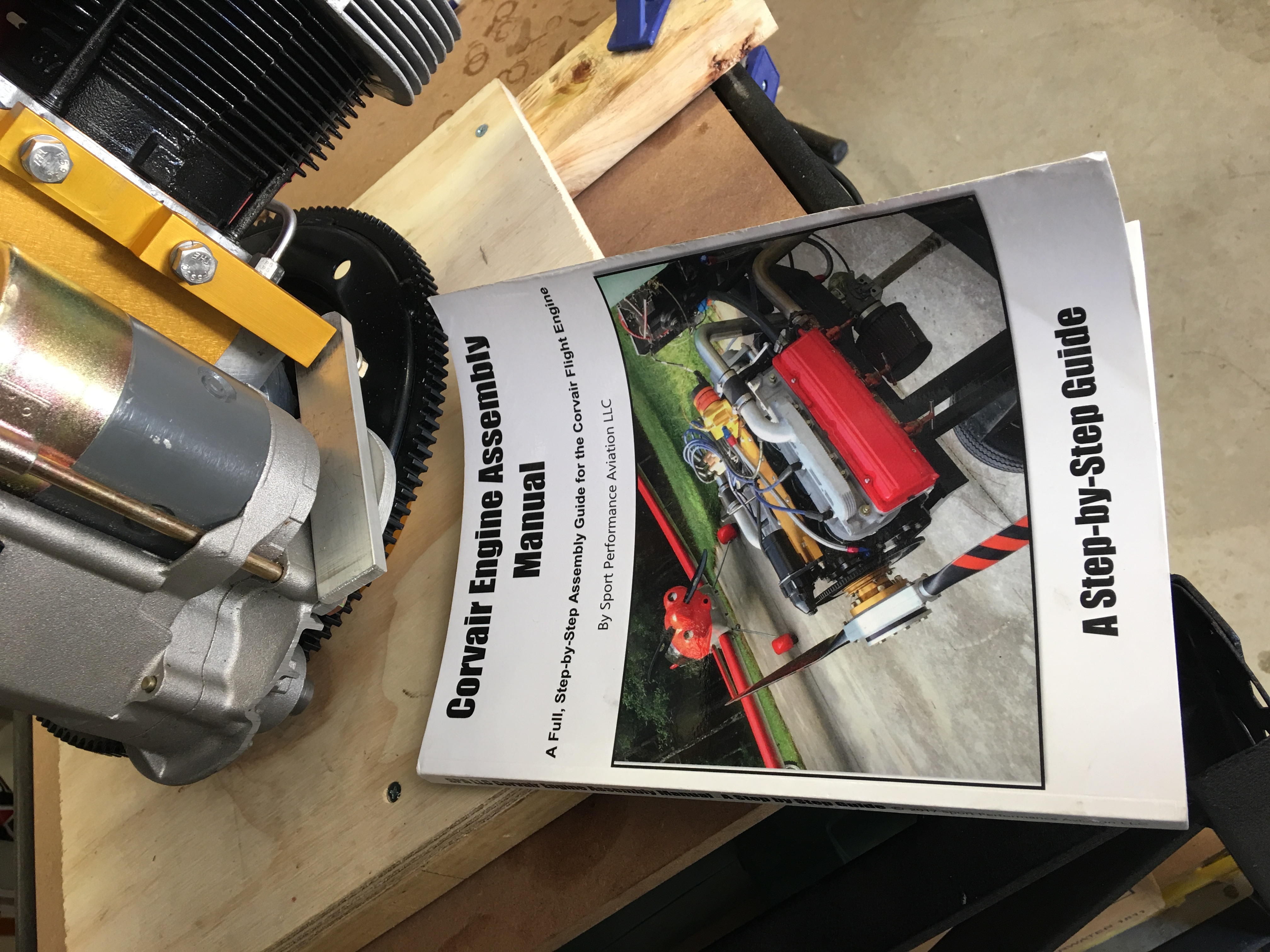
Corvair Engine Build
Oshkosh Corvair display click here...
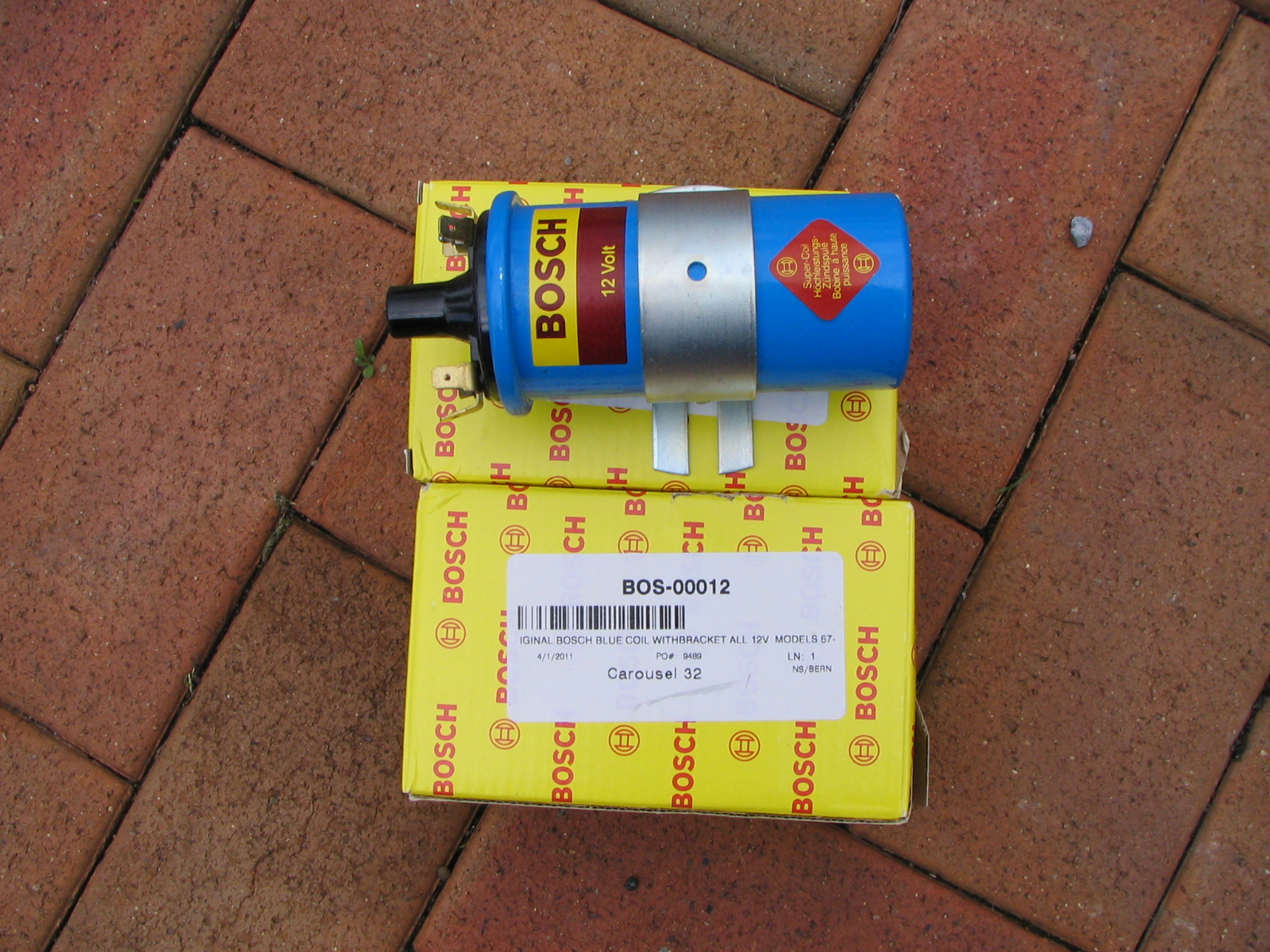
- Electronic & points, dual coil ignition system with a coil switching device to offer some kind of redundancy should either electronic or points, or one of the coils decide to go south! These are the 2 parts in the ignition system which are affected by heat and the most likely to fail out of all the individual igniton parts. Will be using the Bosch blue coils.
- I will be installing a deepened oil pan to allow the carriage of extra oil. In conjunction with this a modified oil pick up will be used.
- The standard cast pistons are not up to the job in an aeroconversion so forged pistons will be used.
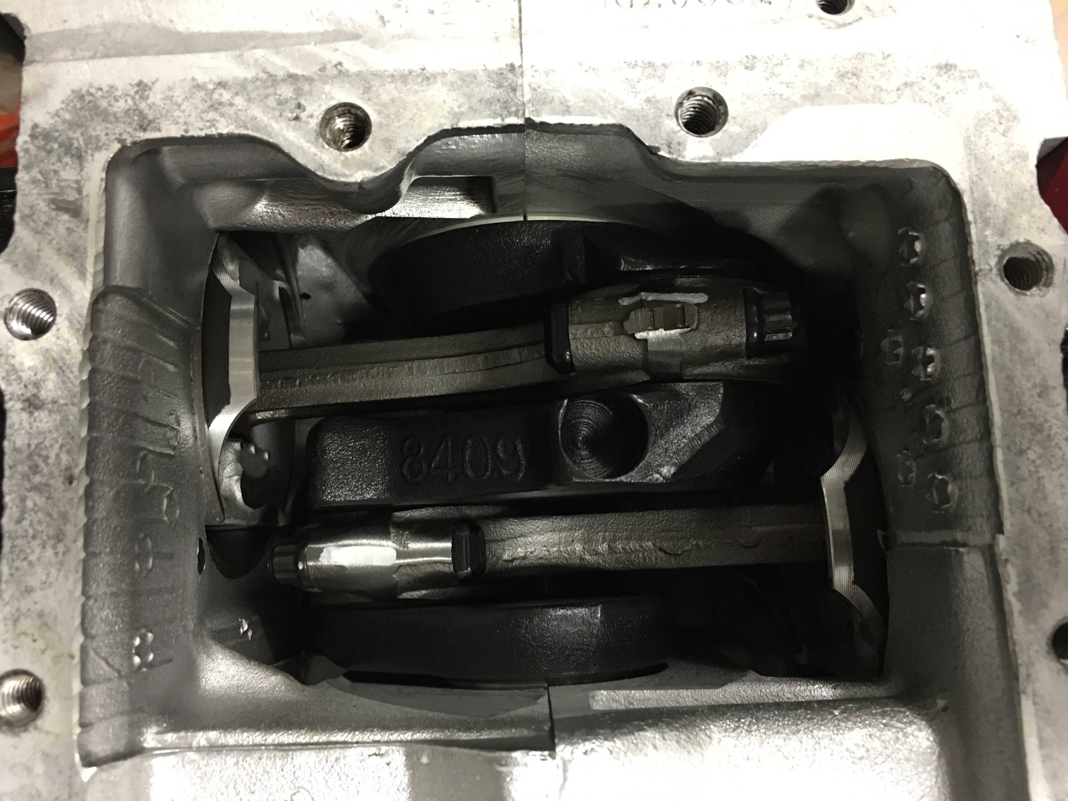
- Forged and balanced rods with ARP bolts.
- OT10 Cam.
- I will install a 5th bearing to offer additional support to the crank. There have been a number of builds where the cranks have cracked. I will also Nitride the crank.
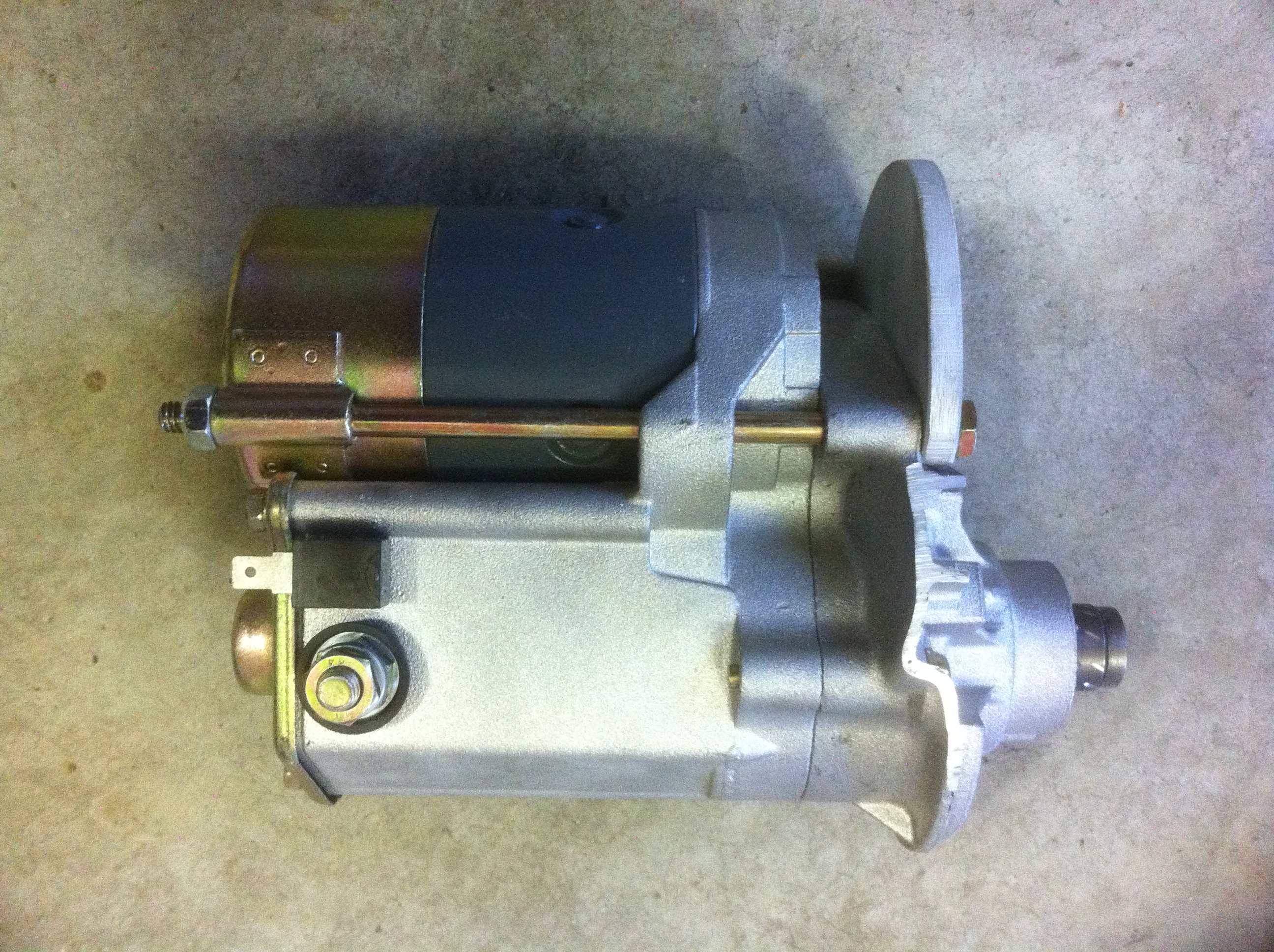
- John Deere "Dynamo" and regulator.
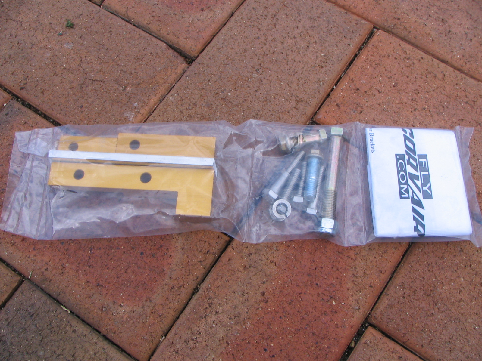
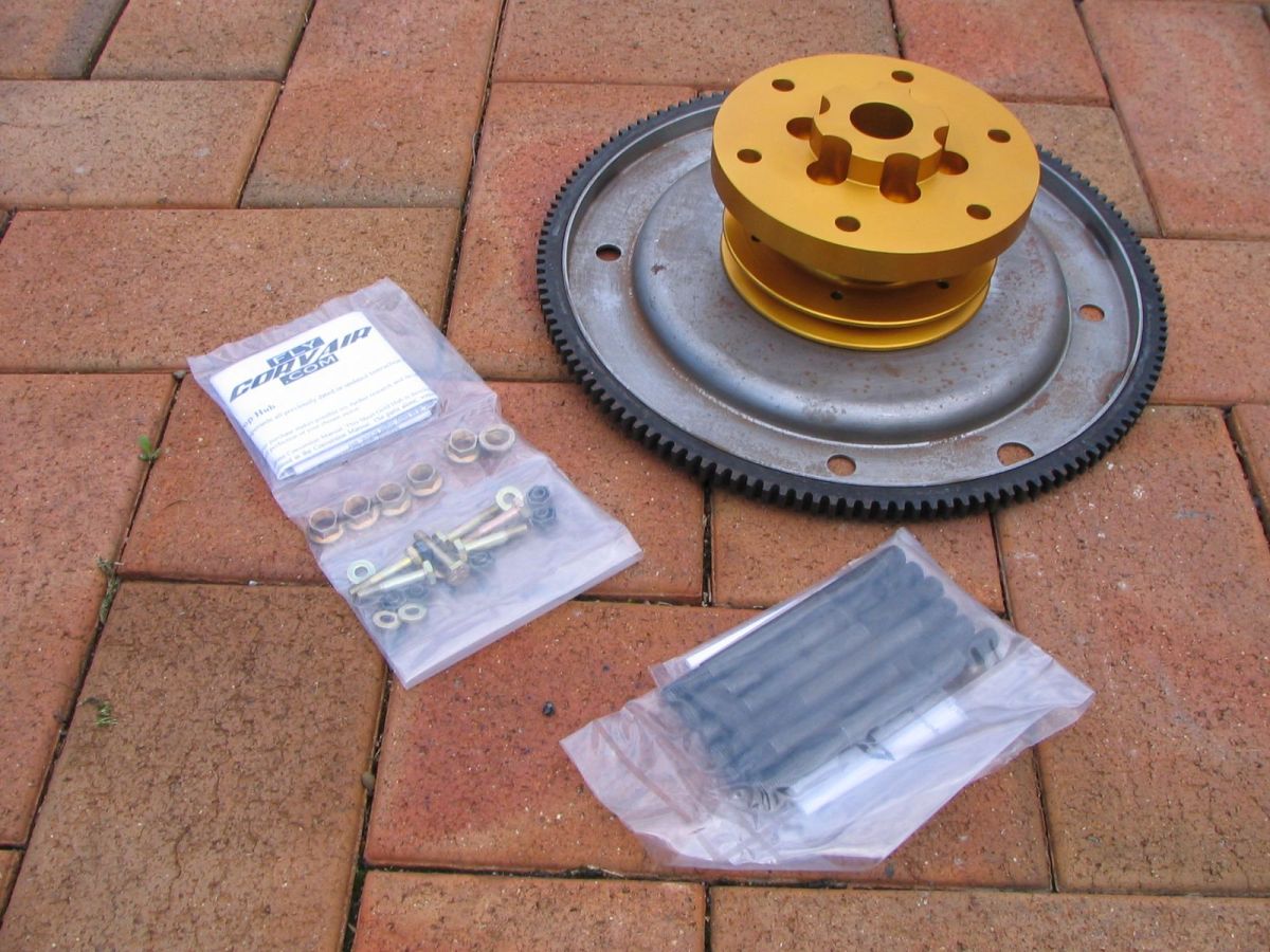
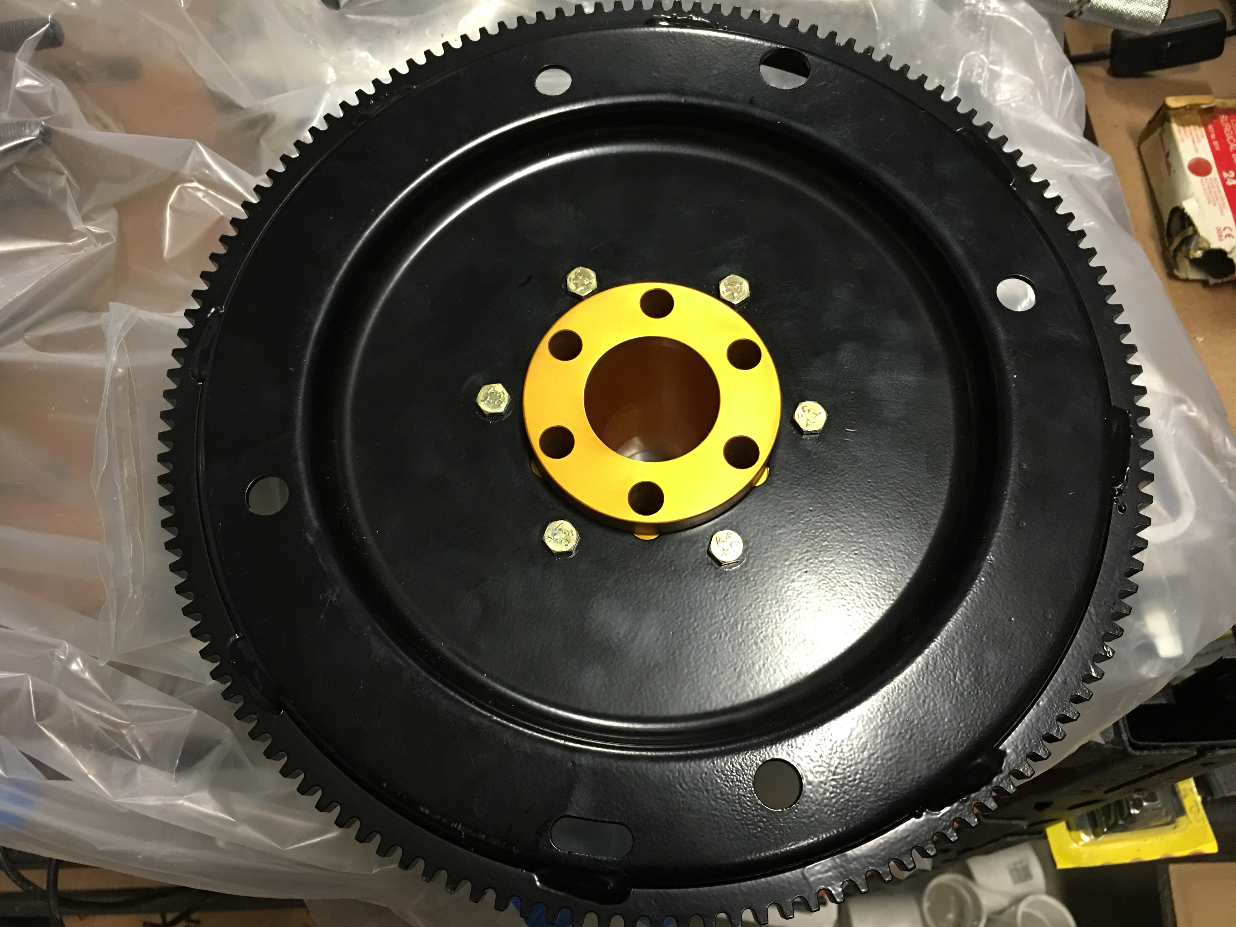
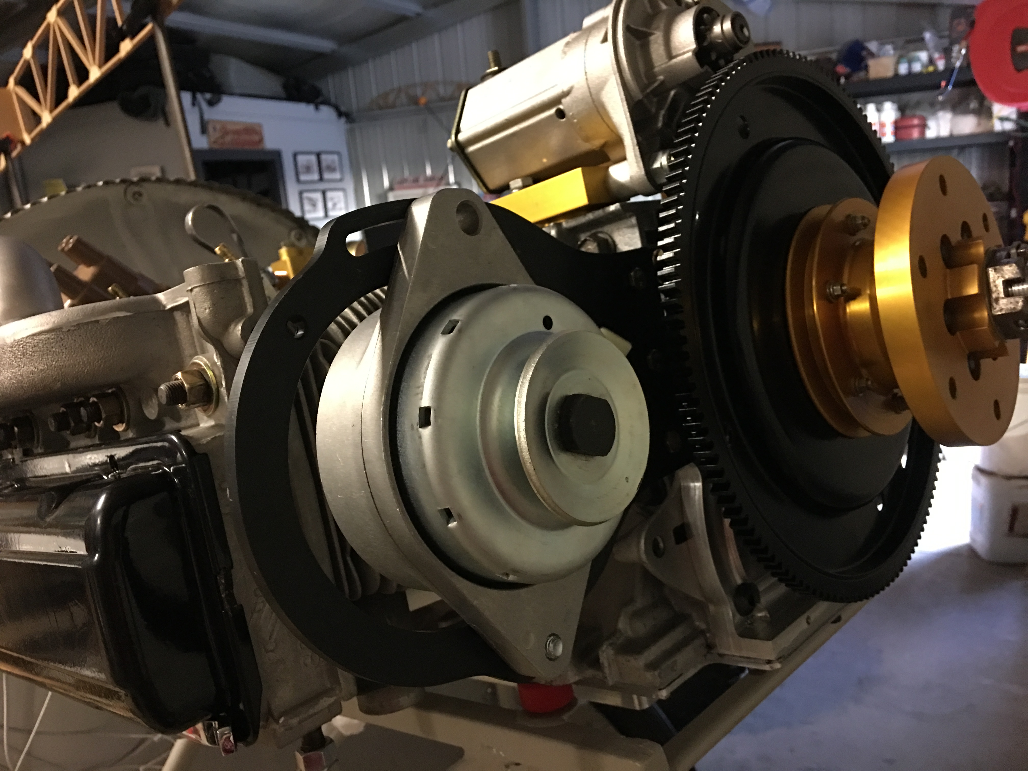
- William Wynne front starter assembly, safety shaft and gold prop hub.
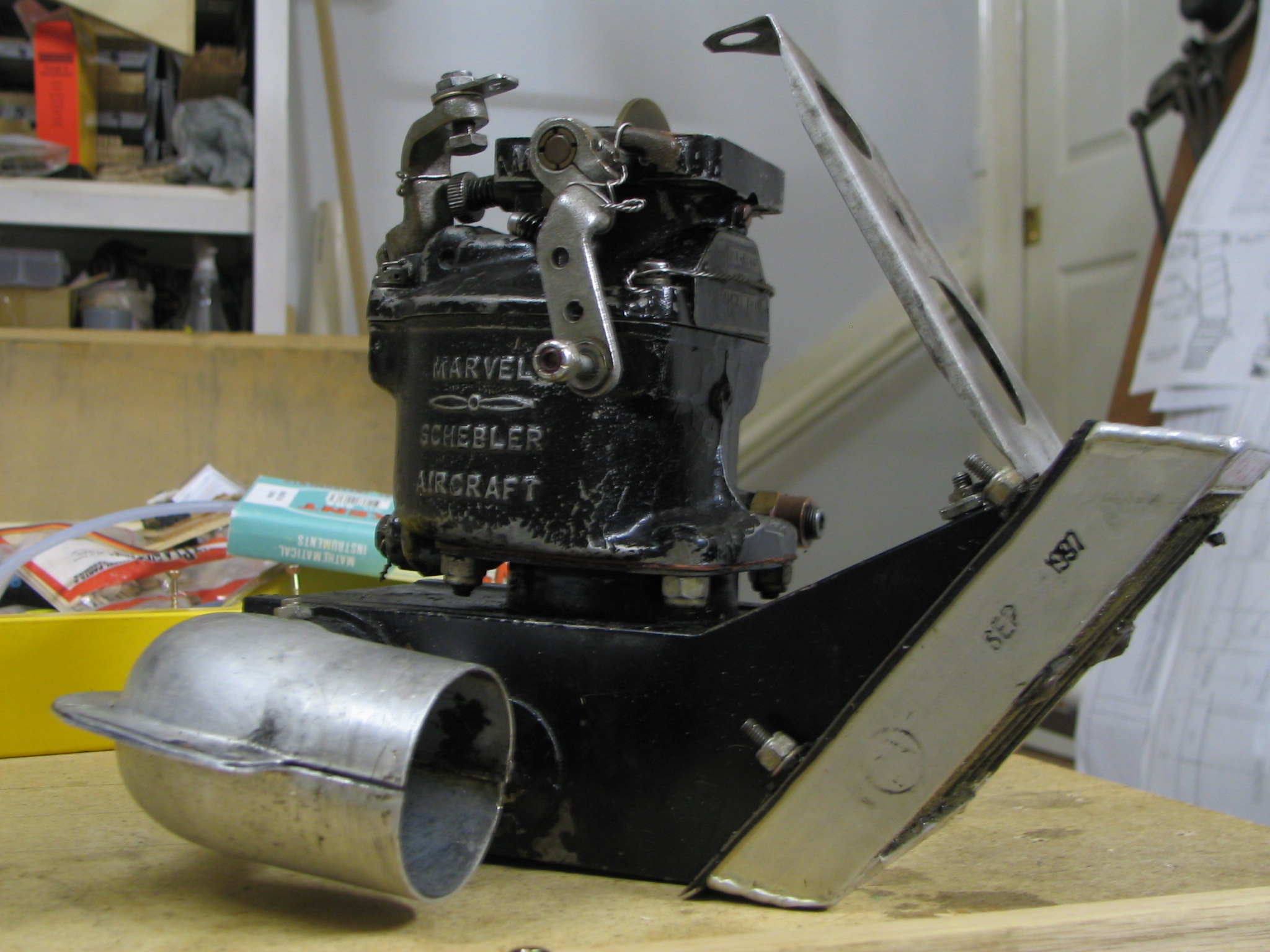
- I was going to go with a Rotec slide carb but have since heard there have been some hiccups with them on the Corvair. I am going to play it safe and use the MA-3SPA from a Continental O-200. Part number 10-4894.
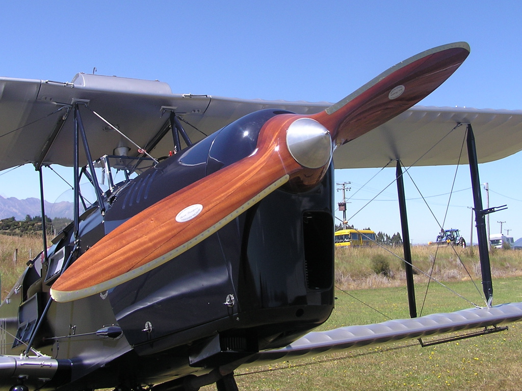
- Propellor will at first be a carbon fibre Warp Drive 66 inch ground adjustable 2 blade. Eventually, once the aircraft has been flight tested, I would like to look at a wooden prop.
A Warp Drive and a Thompson Wooden Prop
Bare bones Chevrolet Corvair engine block is here!
*Update: - DO NOT buy anything from LS Corvair. I was assured that this block below had not been blast cleaned in any way. When it arrived here I took it in to my local engine reconditioning shop to see about having it chemically cleaned and he took one look at it and said "he wouldnt rebuild that for a car let alone a plane". Anyone need a boat anchor?*
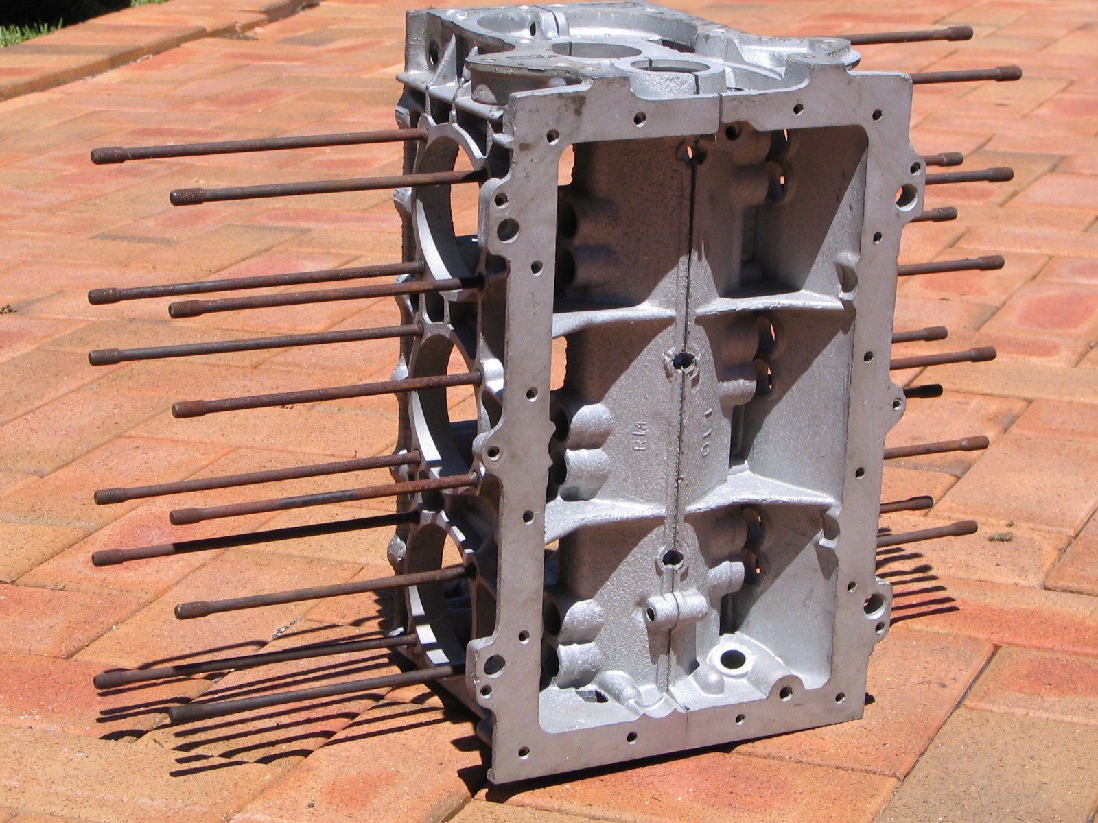
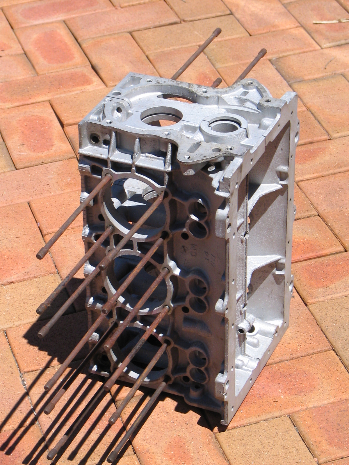
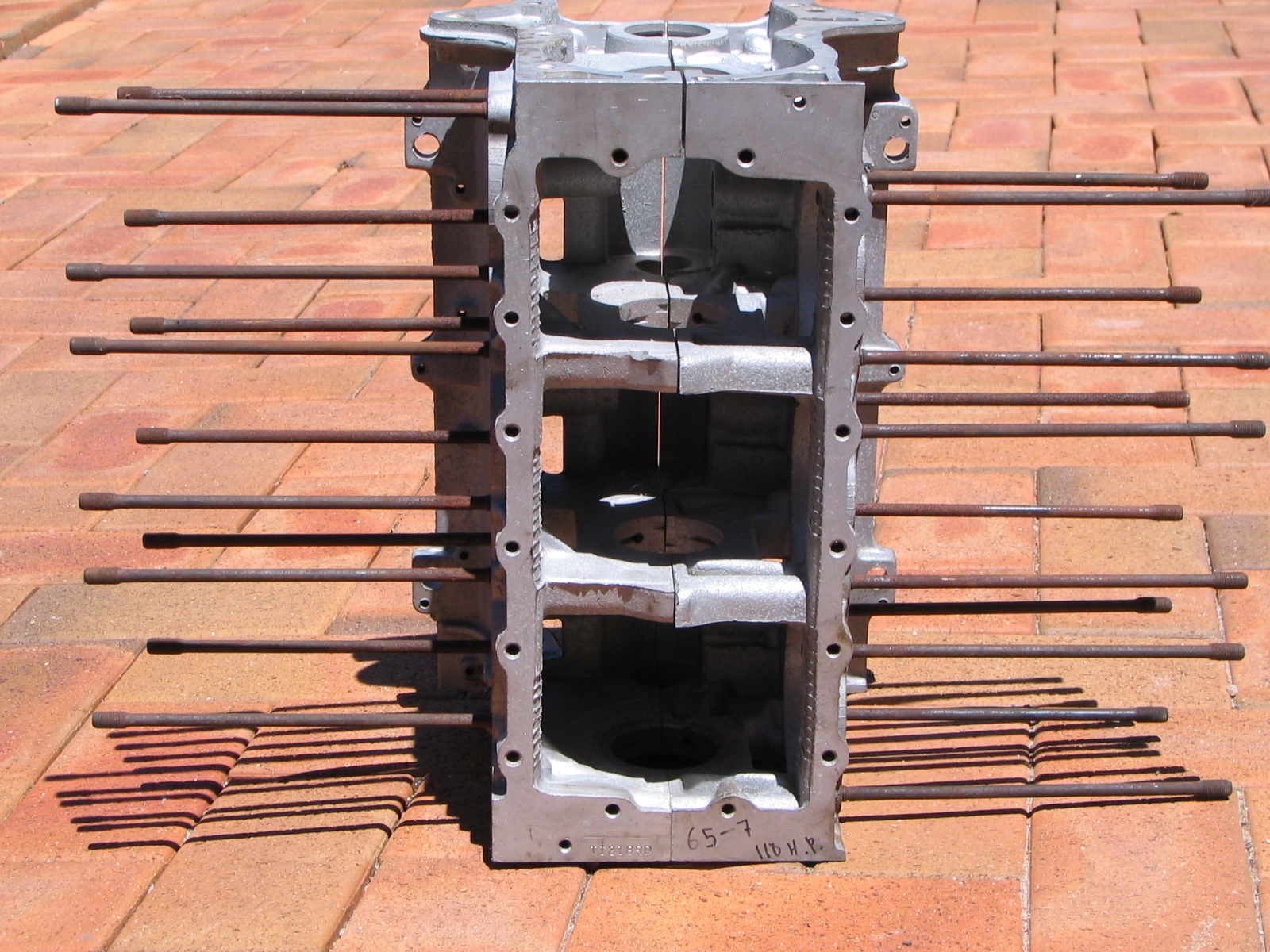
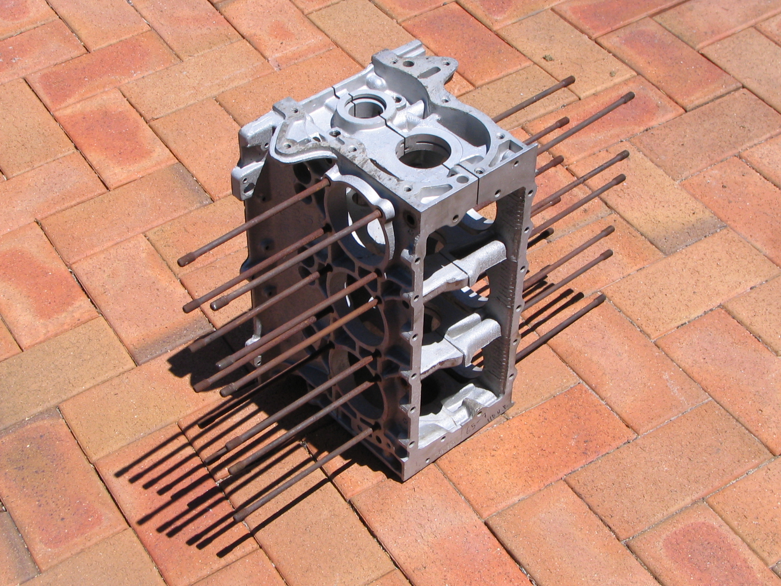
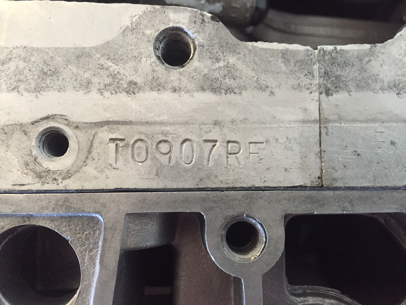
Block Number TI2I8RD
Year 1965, 110HP, 164ci
After voicing my frustration at LS Corvair on a Corvair forum I received an email from Steve Kurash who probably felt sorry for me :o)
Steve kindly suggested he be my in between man in the USA and he had a spare Corvair core in his garage that he would deliver to Roy Szarafinski for inspection to make sure it will be a suitable core for rebuild. This was organised and Roy gave me the go ahead. It is sitting in Roy's workshop now awaiting Roy to rebuild the bottom end. Once he has had the crank modified and fitted an OT-10 cam and fitted his fifth bearing he will ship it to me here in Australia. I have most of the other parts here to complete the assembly.
This is an example of a Roy Szarafinski 5th bearing from Roy's Garage.
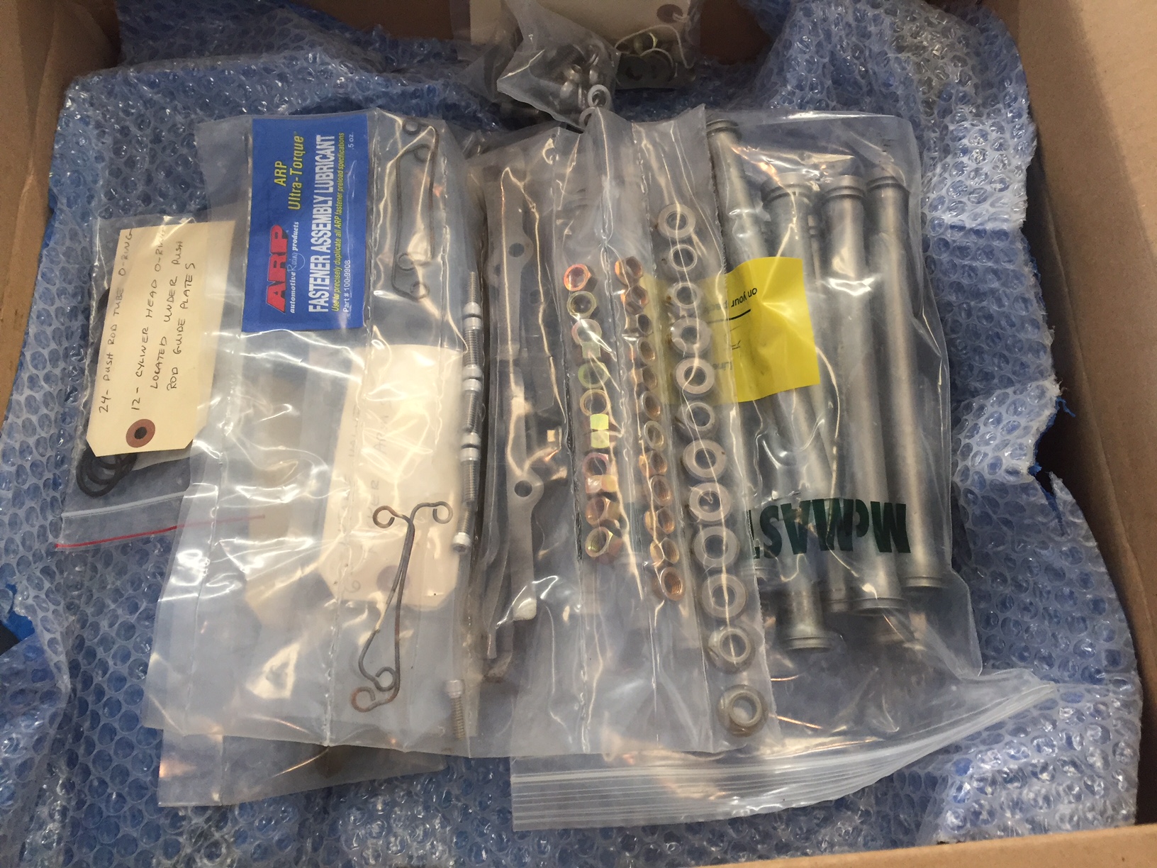
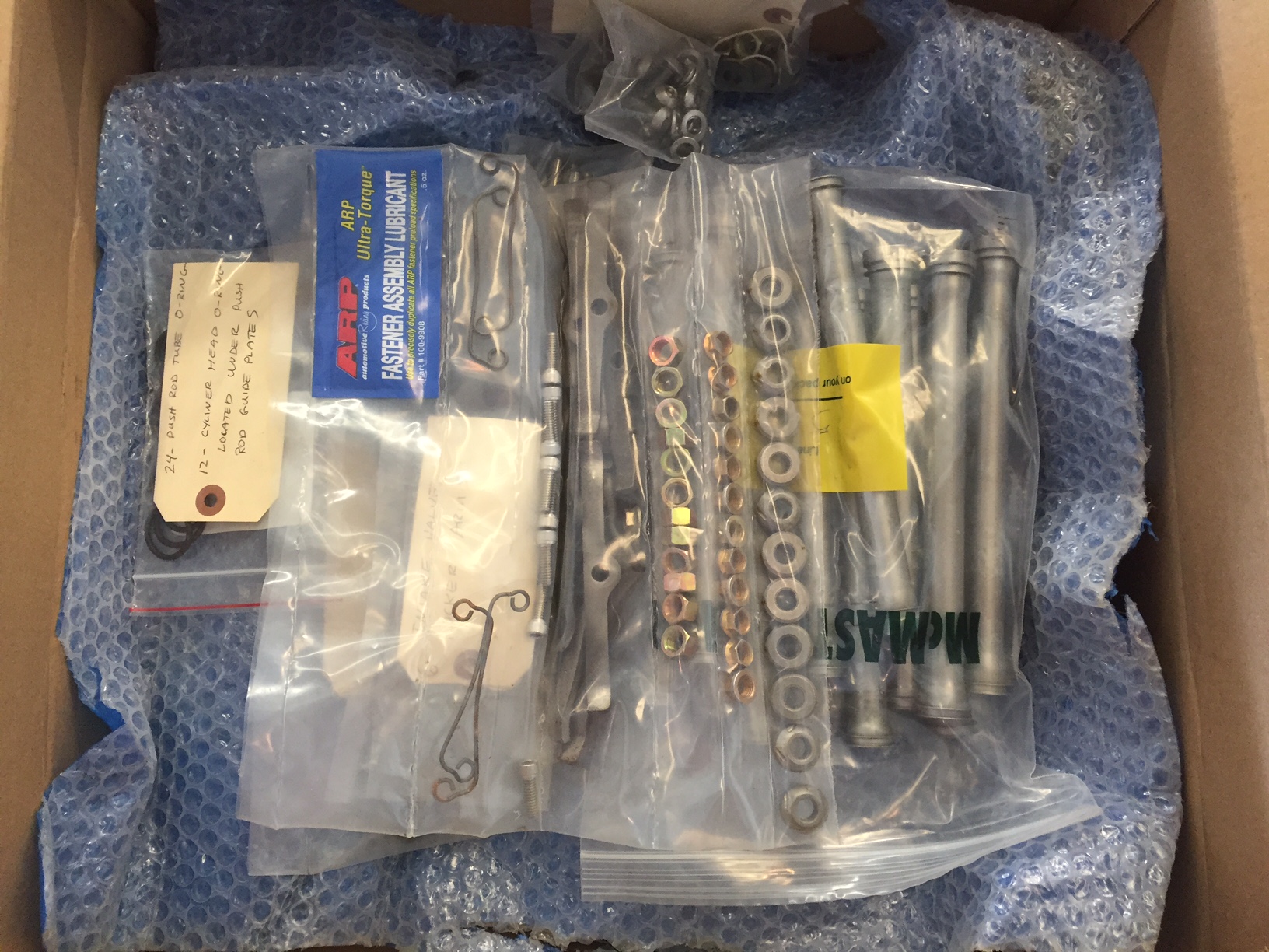
A little brown box arrived from the USA with a pile of Corvair engine parts from Fred. Fred contacted me by email offering what parts I wanted from several old model engine cores he had there. I went through the Clarks Catalogue and found which parts were common to the old and new model Corvair engines and Fred dismantled, cleaned and sent them to me! I owe Fred a fly some day!
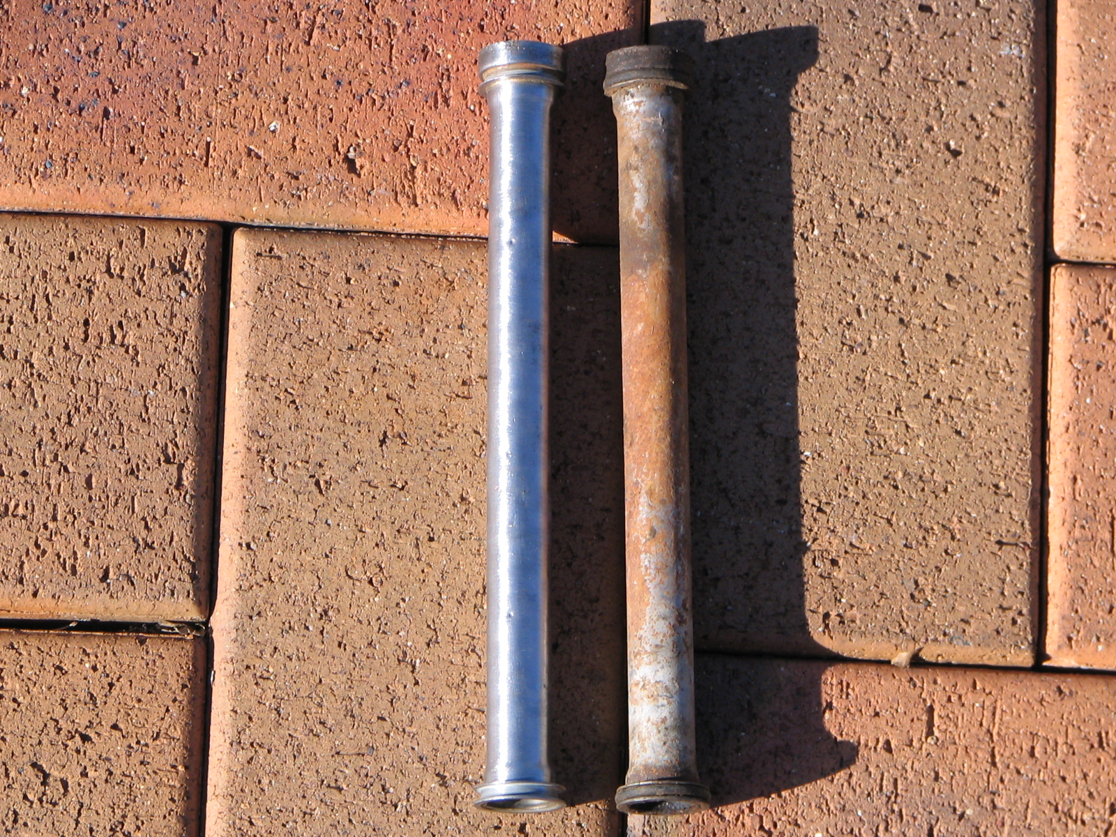
I have posted this photo below to get the opinions from fellow Corvair folk. If you click on the photo you will see the Push rod tube on the left has a flared section on each end, below the O ring. Out of the 12 tubes I have, 2 of them are like this. Any suggestion? Is this normal? Ok to use?

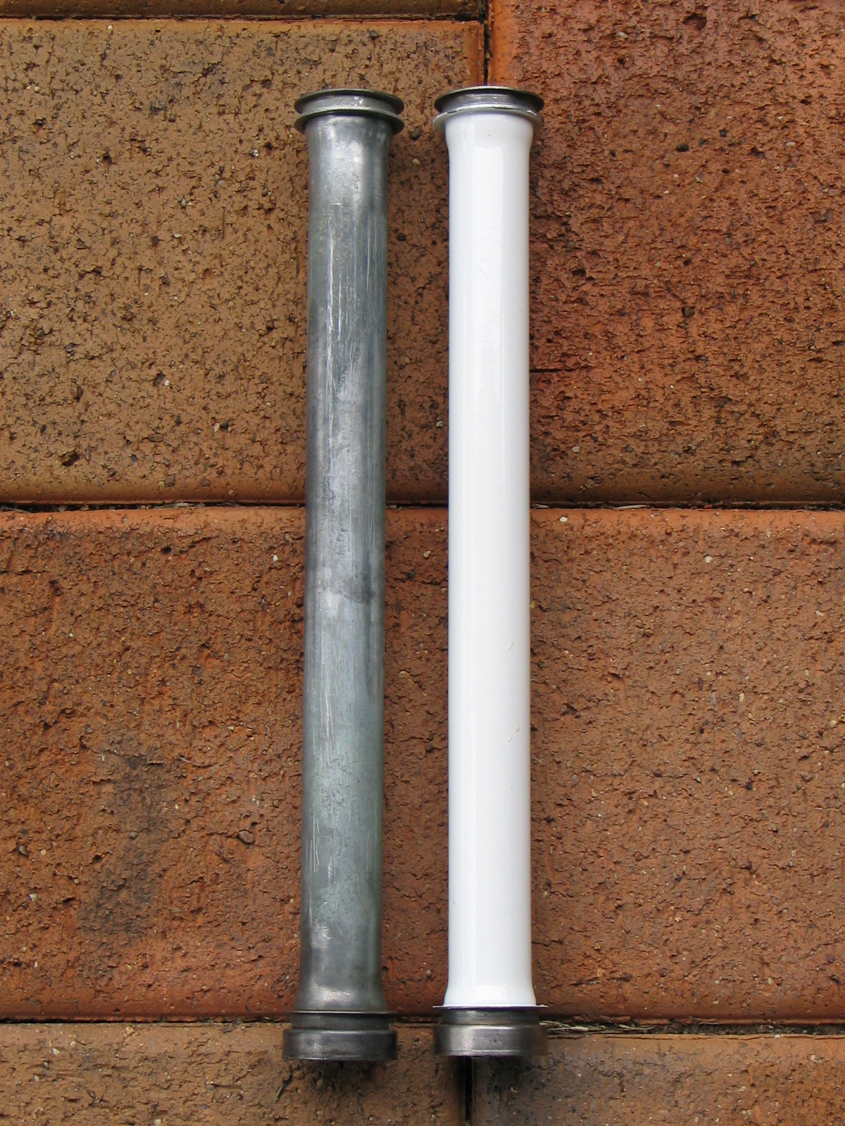
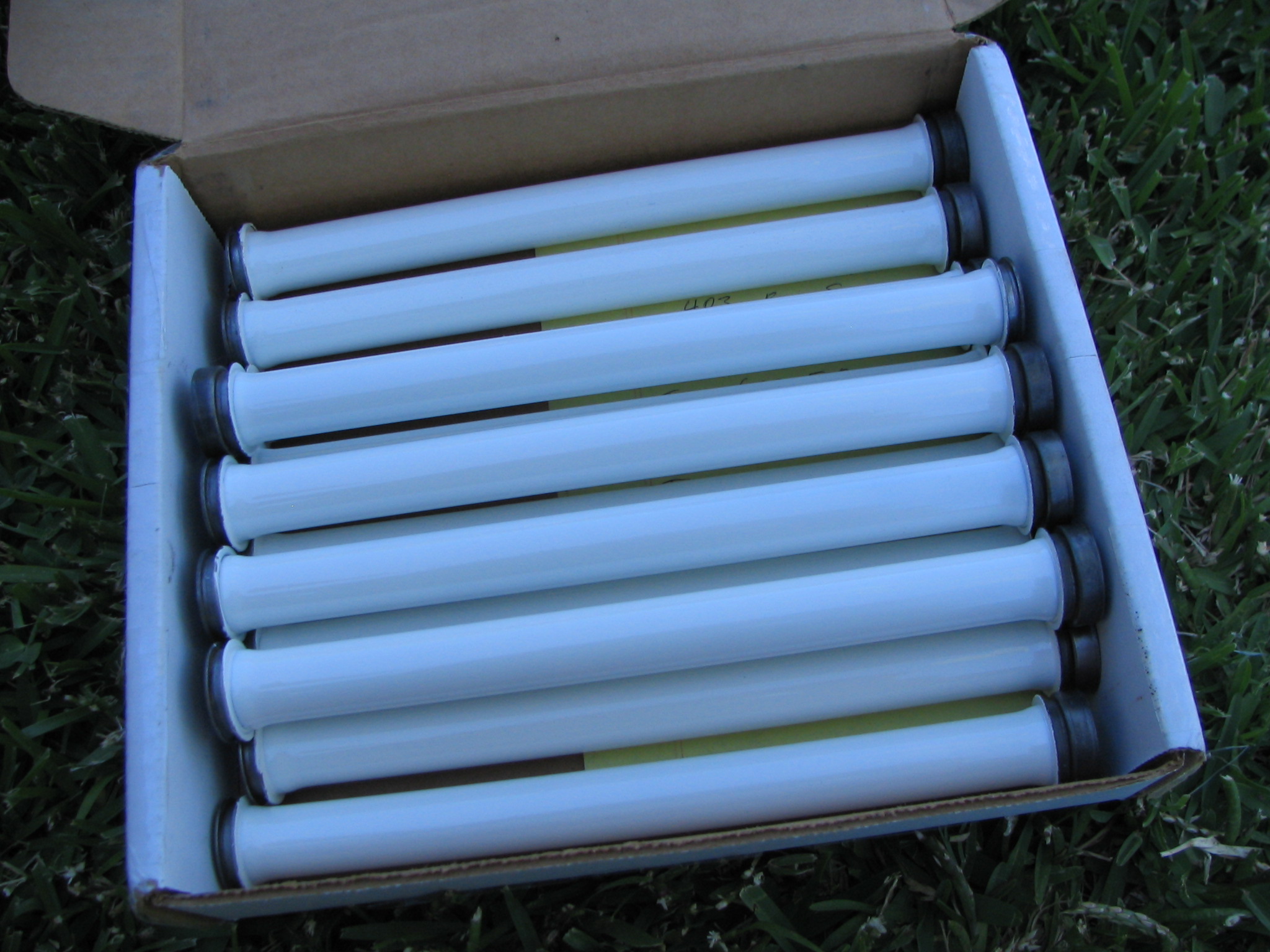
I have been soaking the push rod tubes in solvent degreaser overnight then washing the built up gunk off. Once this is done I dry them with heat to slow down further rusting. I then scuff them with a copper wire brush in an electric drill to remove the surface rust. I then have a copper wire brush in a cylinder shape which I am using to clean and polish the inside of the tubes. All parts of the engine must be spotlessly clean otherwise when it comes time to start, these bits may come loose and end up being spread around the inside of the engine. As can be seen on the tube on the left, I need to clean all the rust out of the O ring channels. This is important to ensure no oil leaks once new Viton seels are fitted when assembling. So far I have cleaned 4 tubes but one of these is not going to be useable due to severe rusting which has made holes.....then to paint them with white VHT high temperature ceramic engine paint.
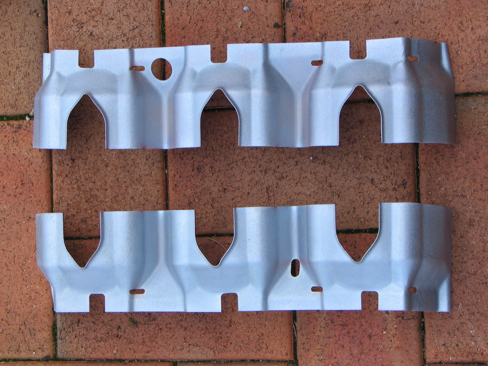
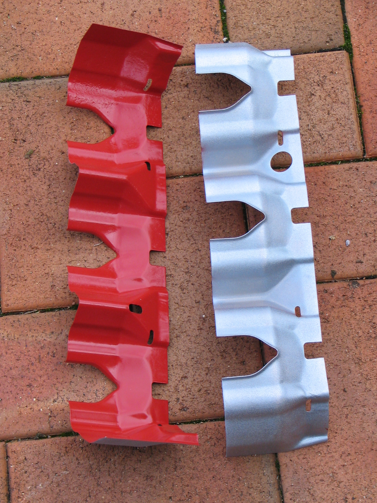
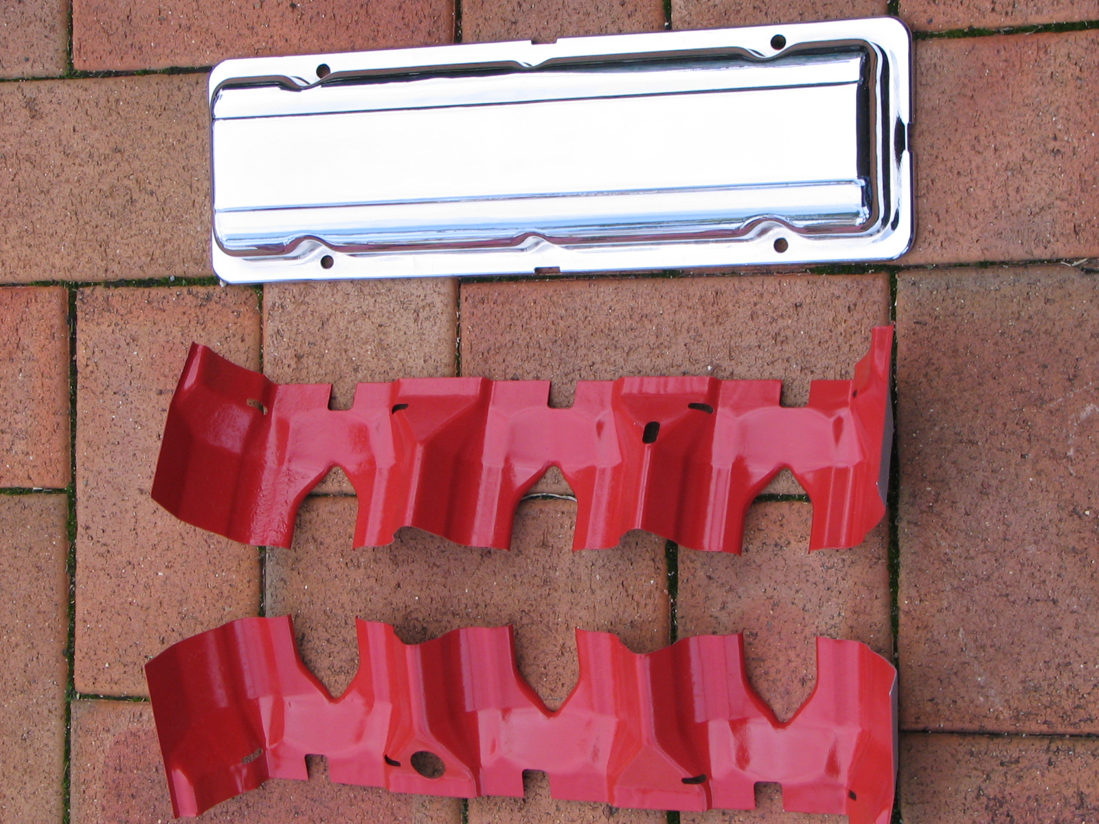
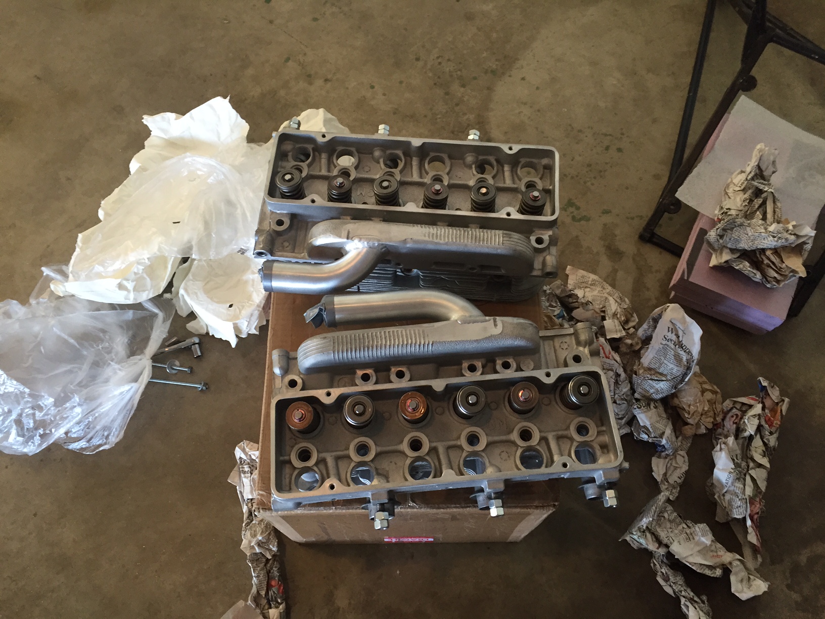
I had the cooling baffles sand blasted, zinc coated and I painted them with VHT paint. Had the rocker covers chromed.


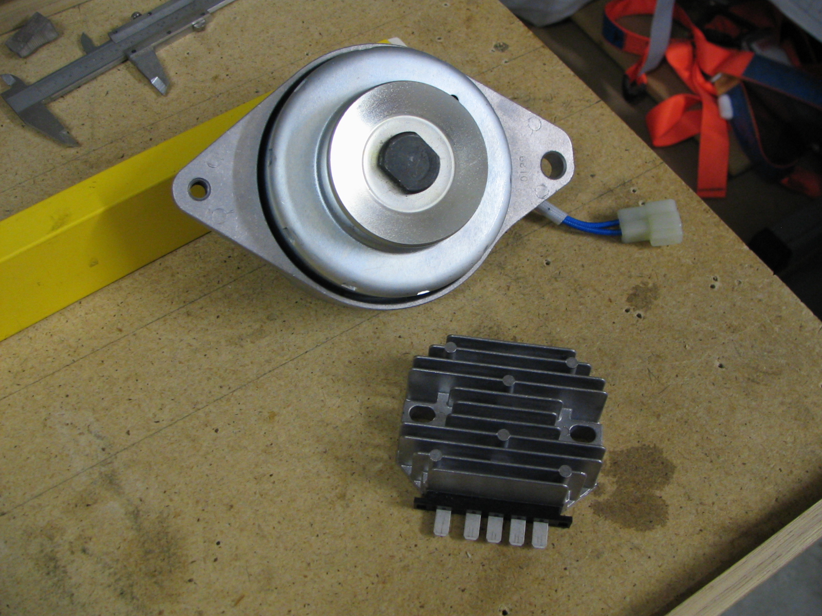
I will be using the tried and tested 20 Amp John Deere dynamo & regulator to charge the battery.
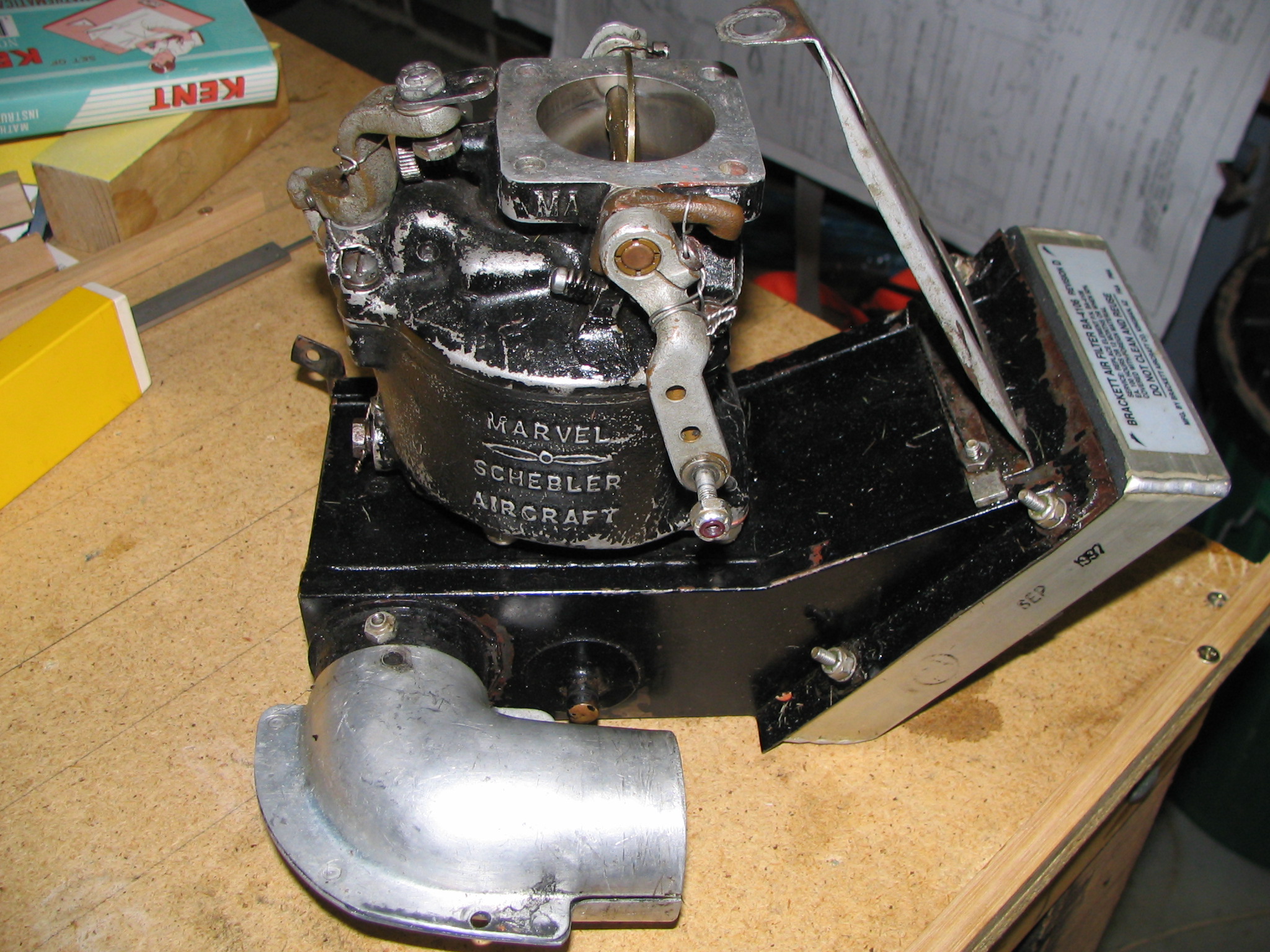
I have decided to use a MA-3SPA carb from a Continental O-200. This is not the 10-4894 we need but is one of a handful that can be easily converted to a 10-4894. This one is a 10-4115-1.
This is William Wynne's modified front starter and mounting brackets. William also has a starter ring gear available that suits his starter motor. Also in these photos is his shortened gold prop hub and hybrid studs which goes with the fifth bearings.

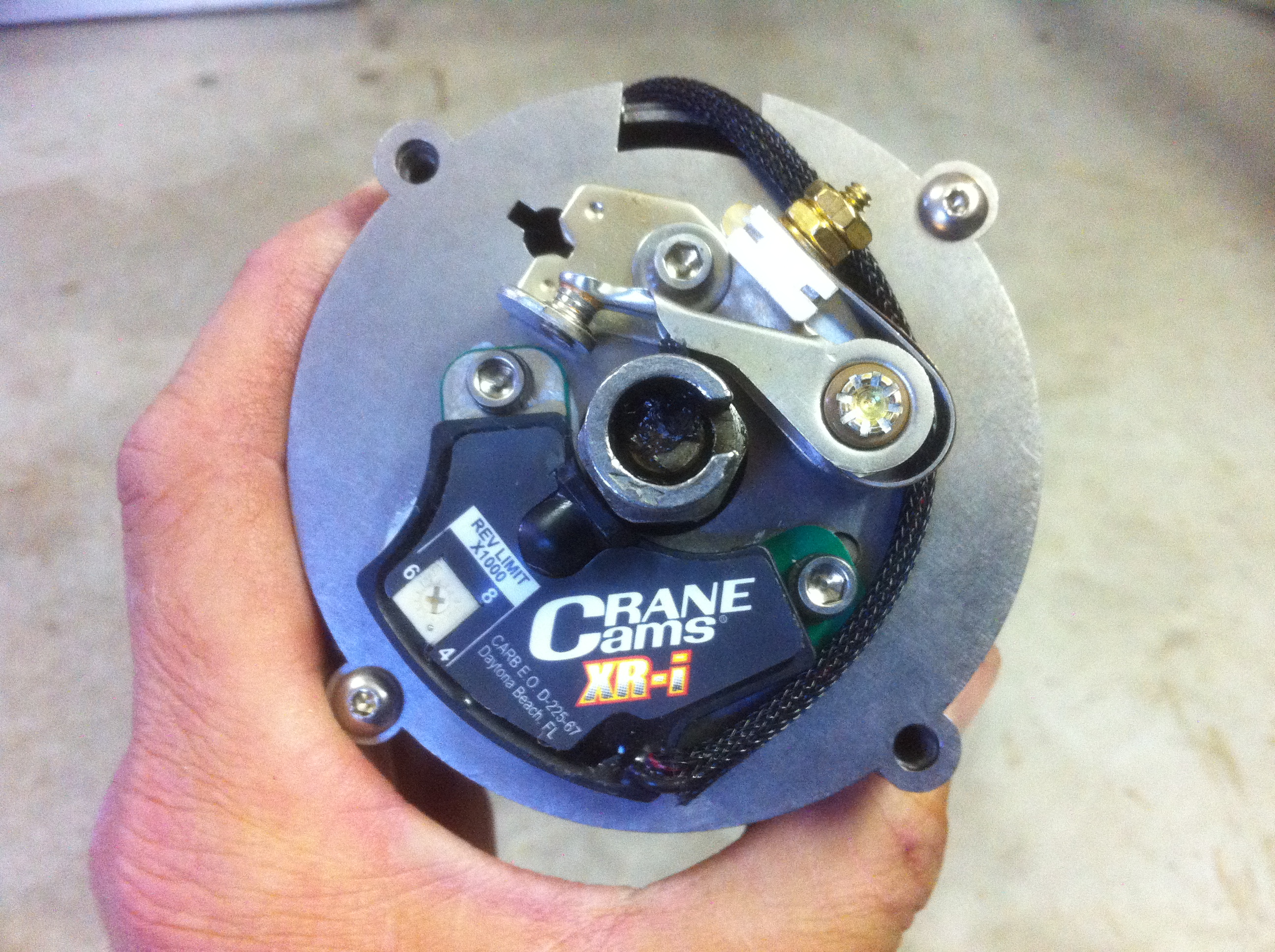
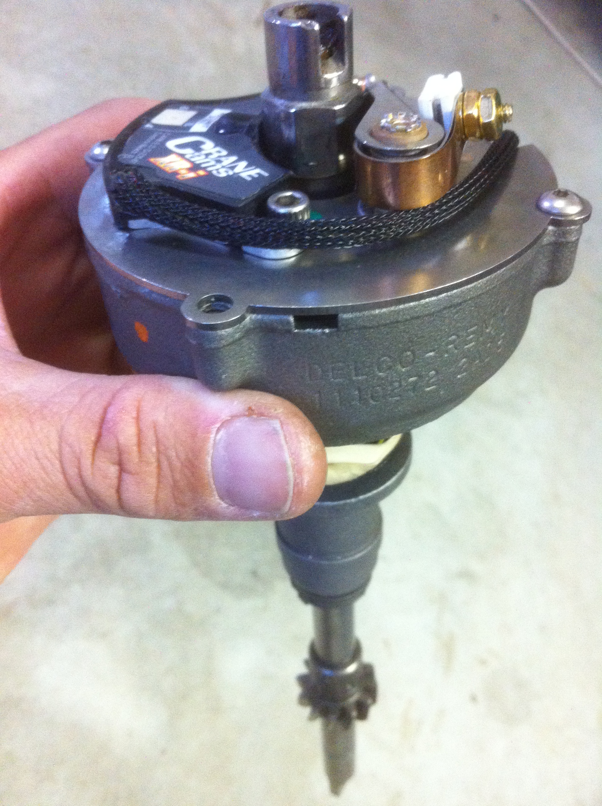
This is William's rebuilt Corvair distributor with dual ignition. One set of points and the other an electronic module. Ignition redundancy seems a good idea to me! By flicking a toggle switch on the instrument panel, I can switch between the two and both options use their own seperate coil.
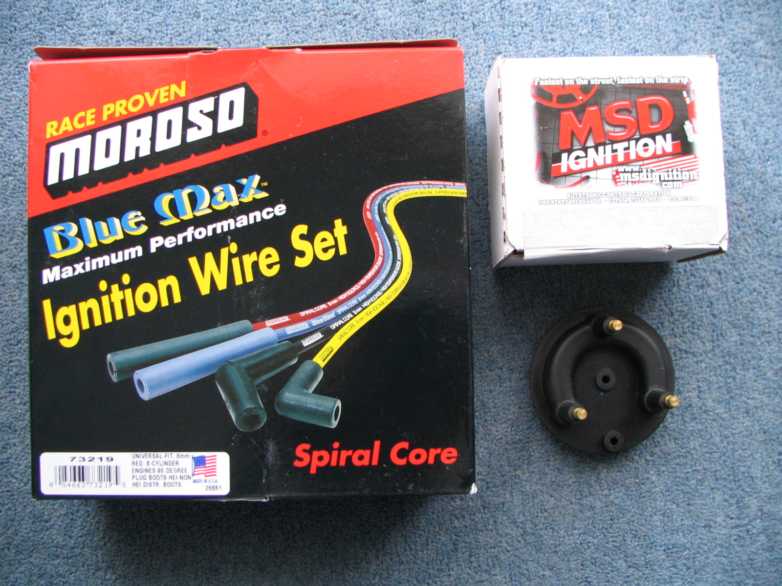
The Original Bosch Blue Coils are epoxy rather than oil filled and have an internal resistor. If your trying to locate these in Australia you are out of luck. I spoke to Bosch Australia who said these were only available in the USA. I am using a MSD coil switcher and Moroso spark leads.
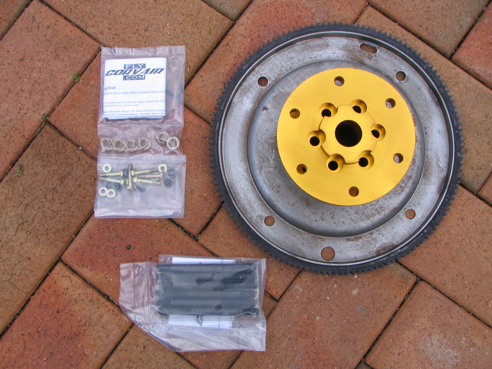
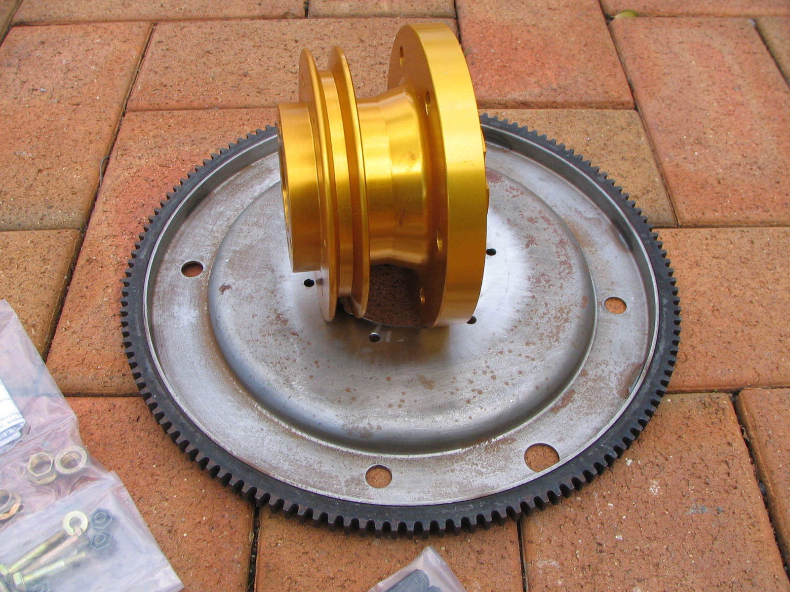
Williams shortend version of the gold hub which is needed when installing a fifth bearing. Also has the pulley groove for the John Deere Dynamo system.
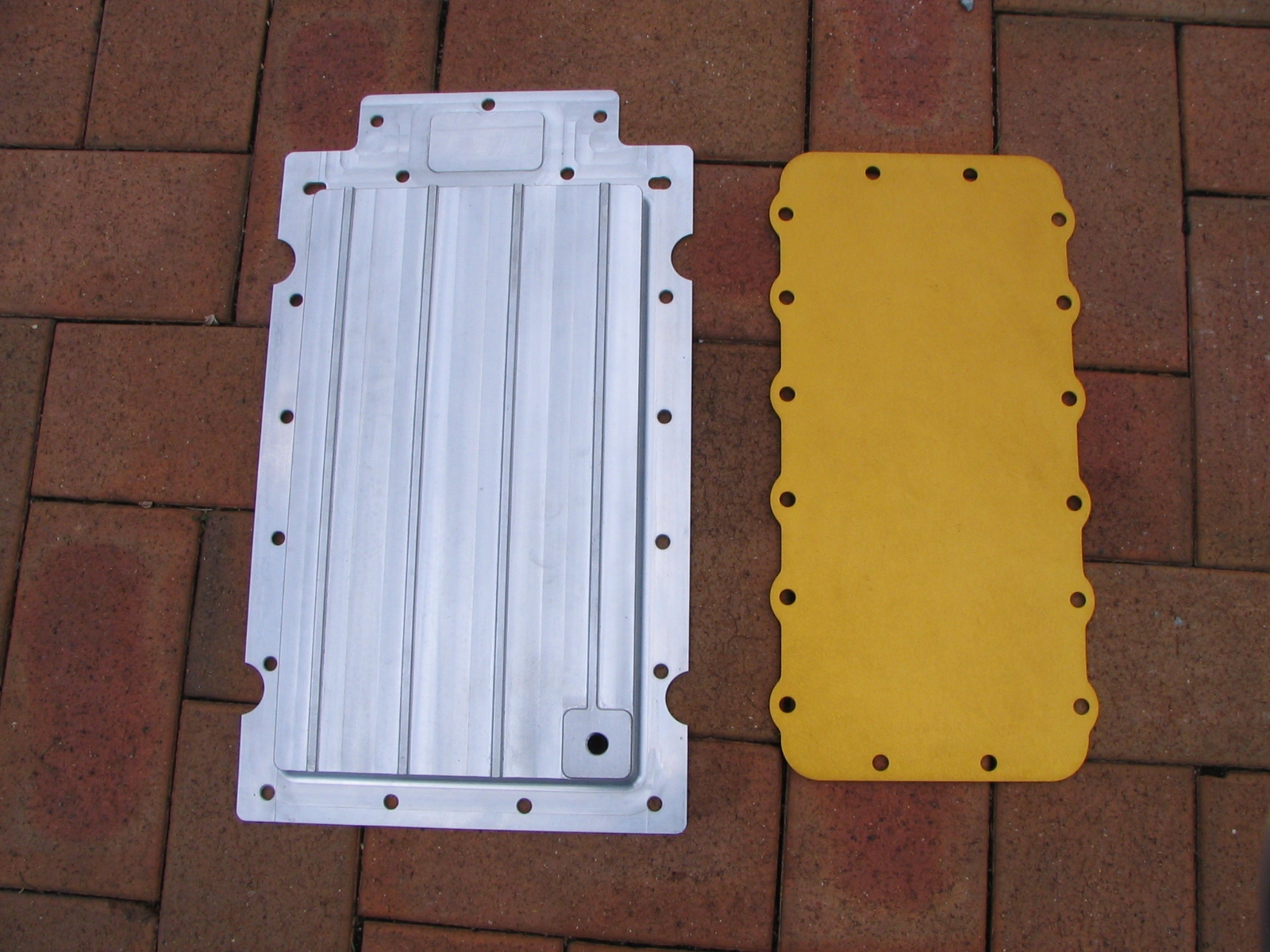
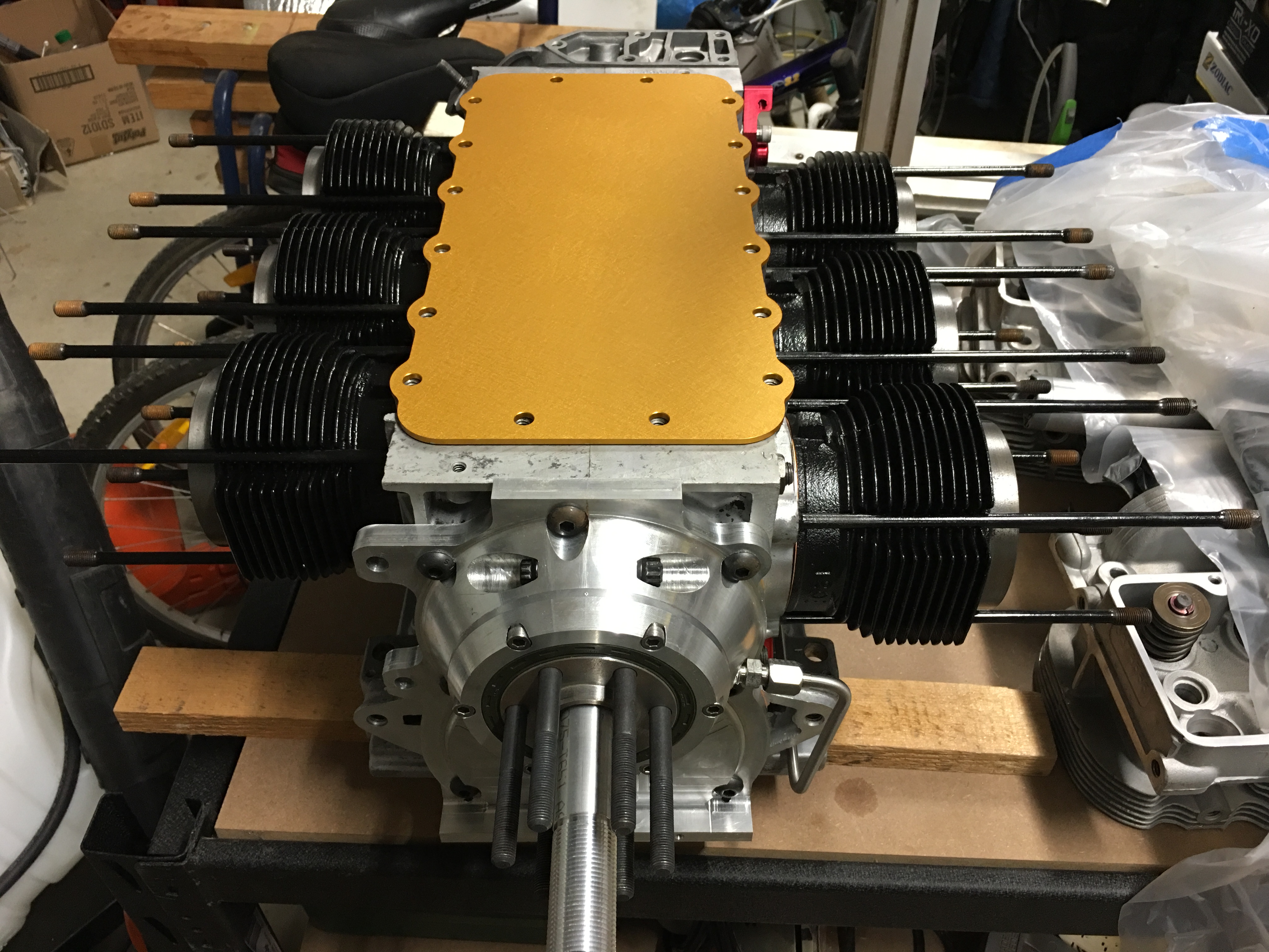
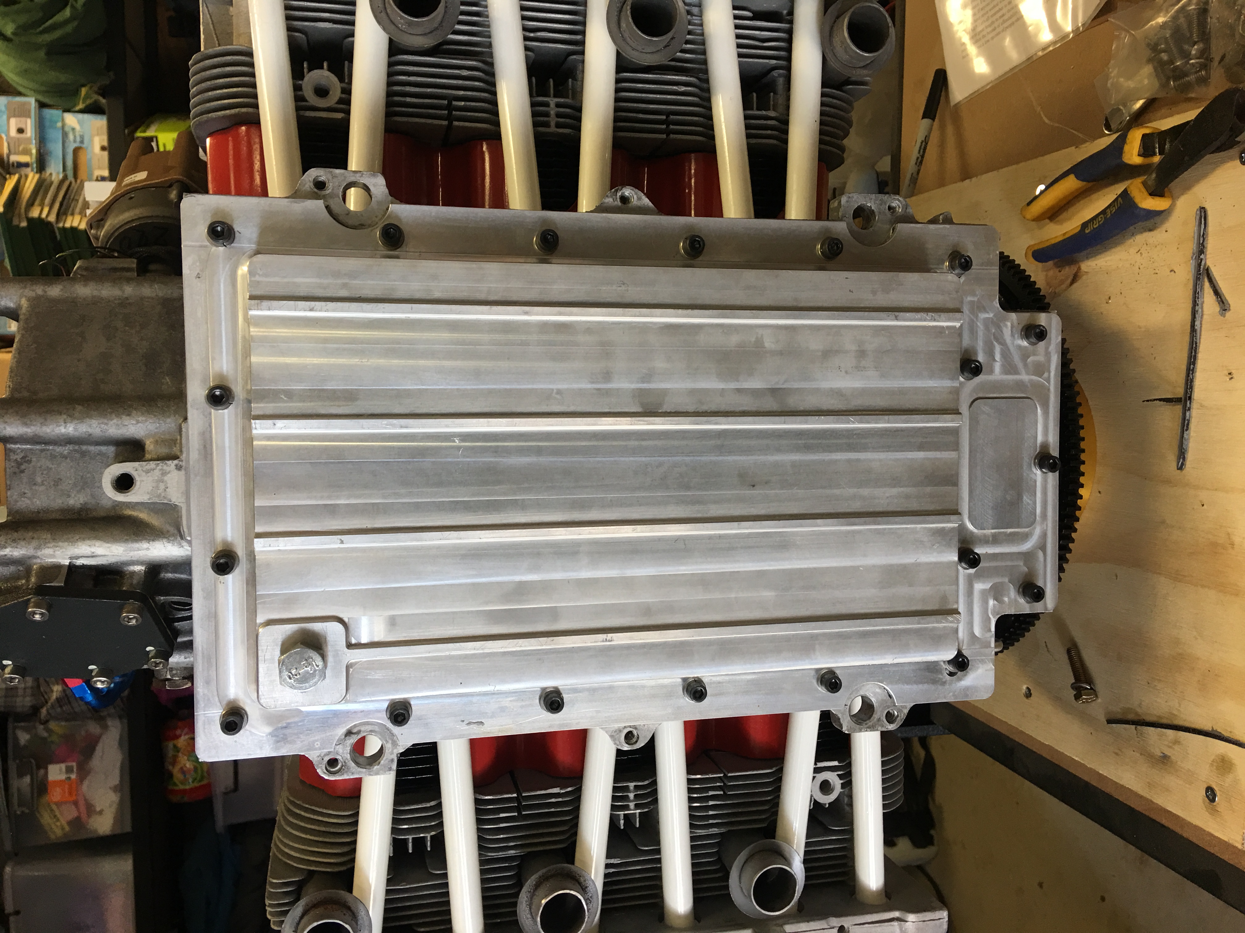
Williams deepened oil pan and gold top cover.

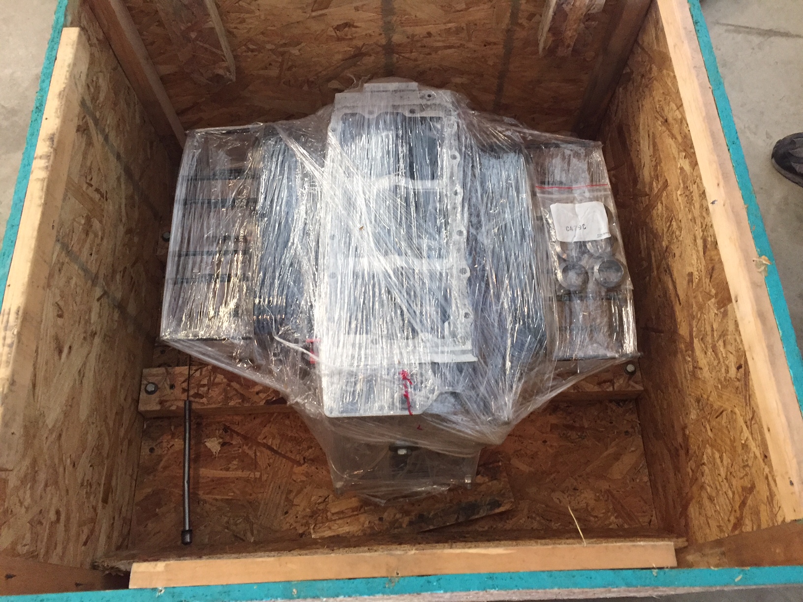
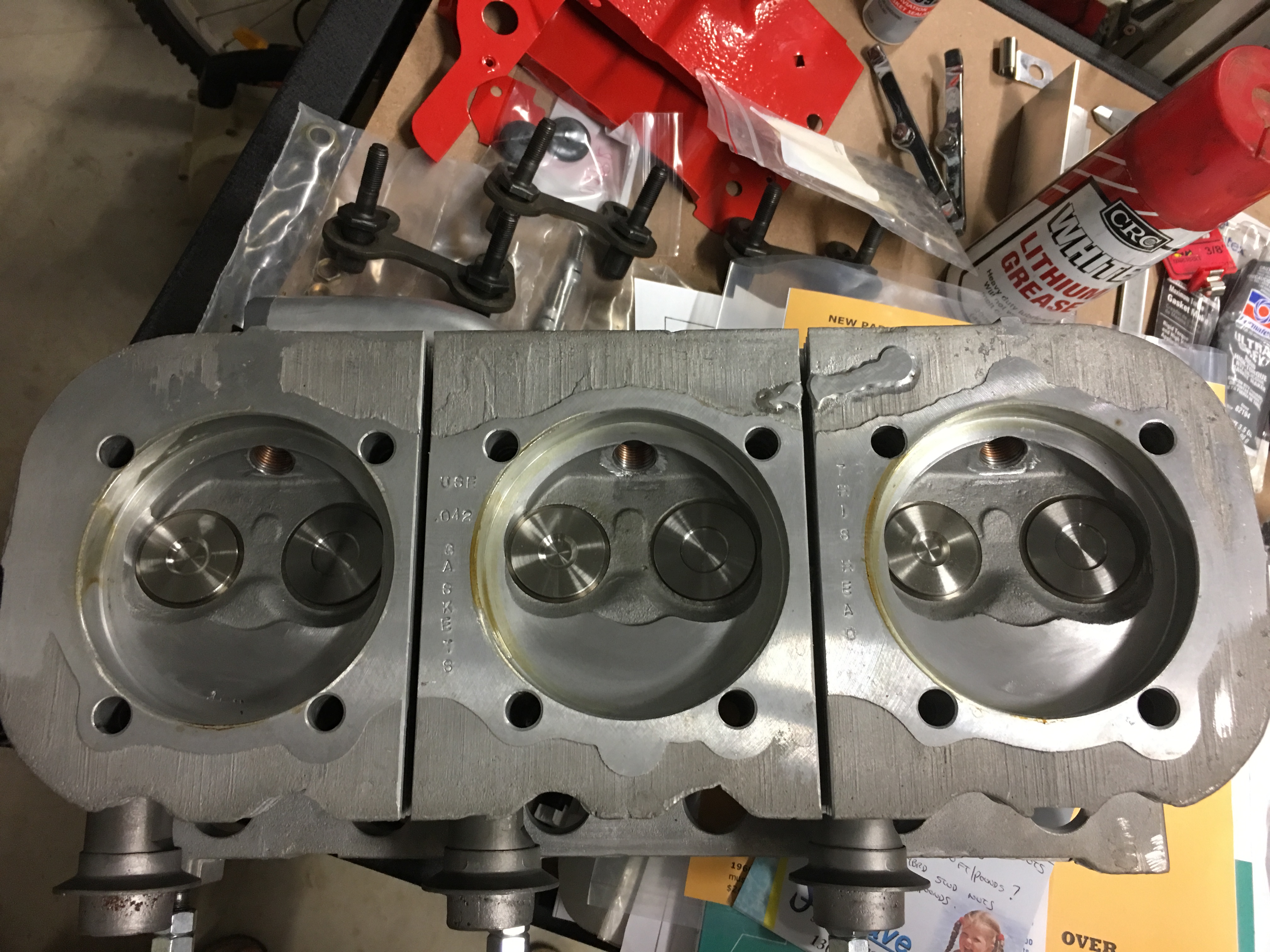
My short block and rebuilt heads ready to ship to Australia.


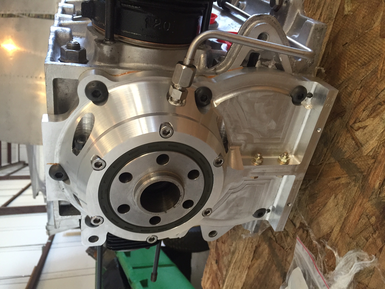
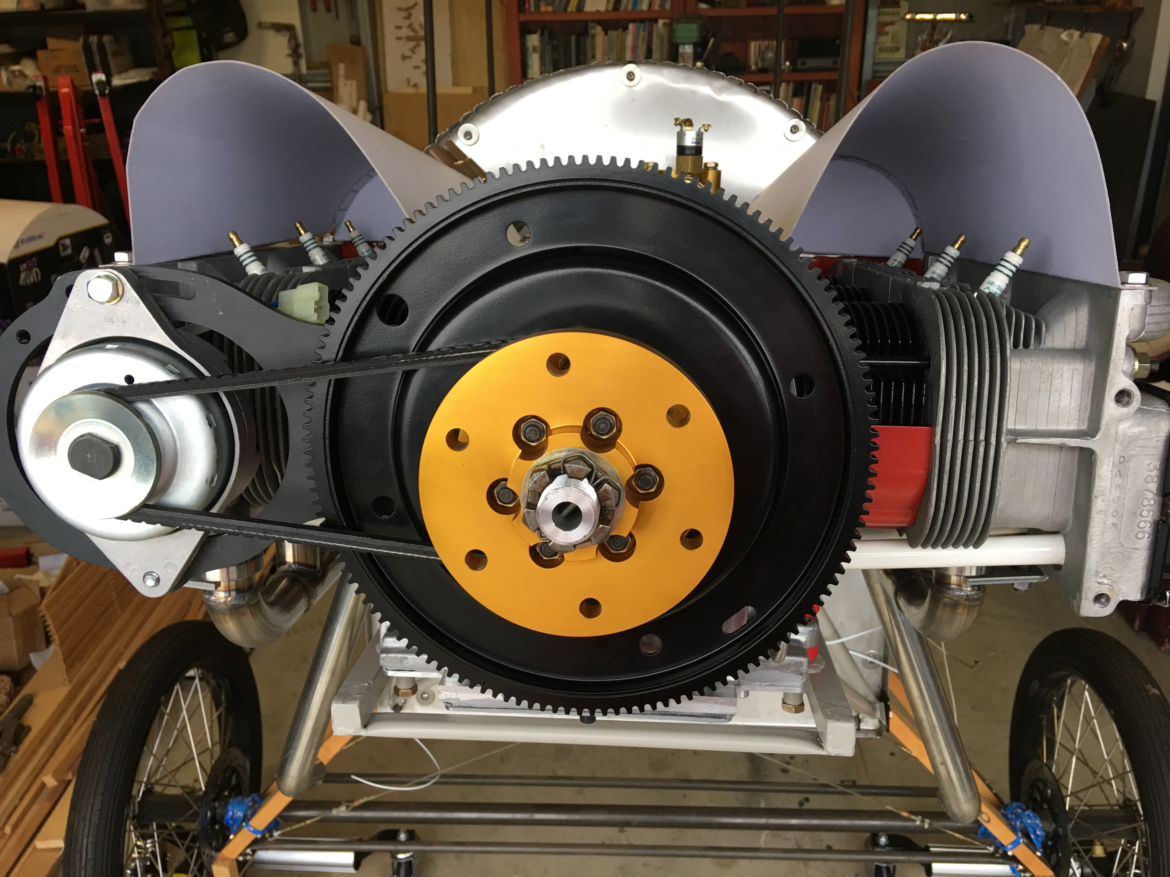
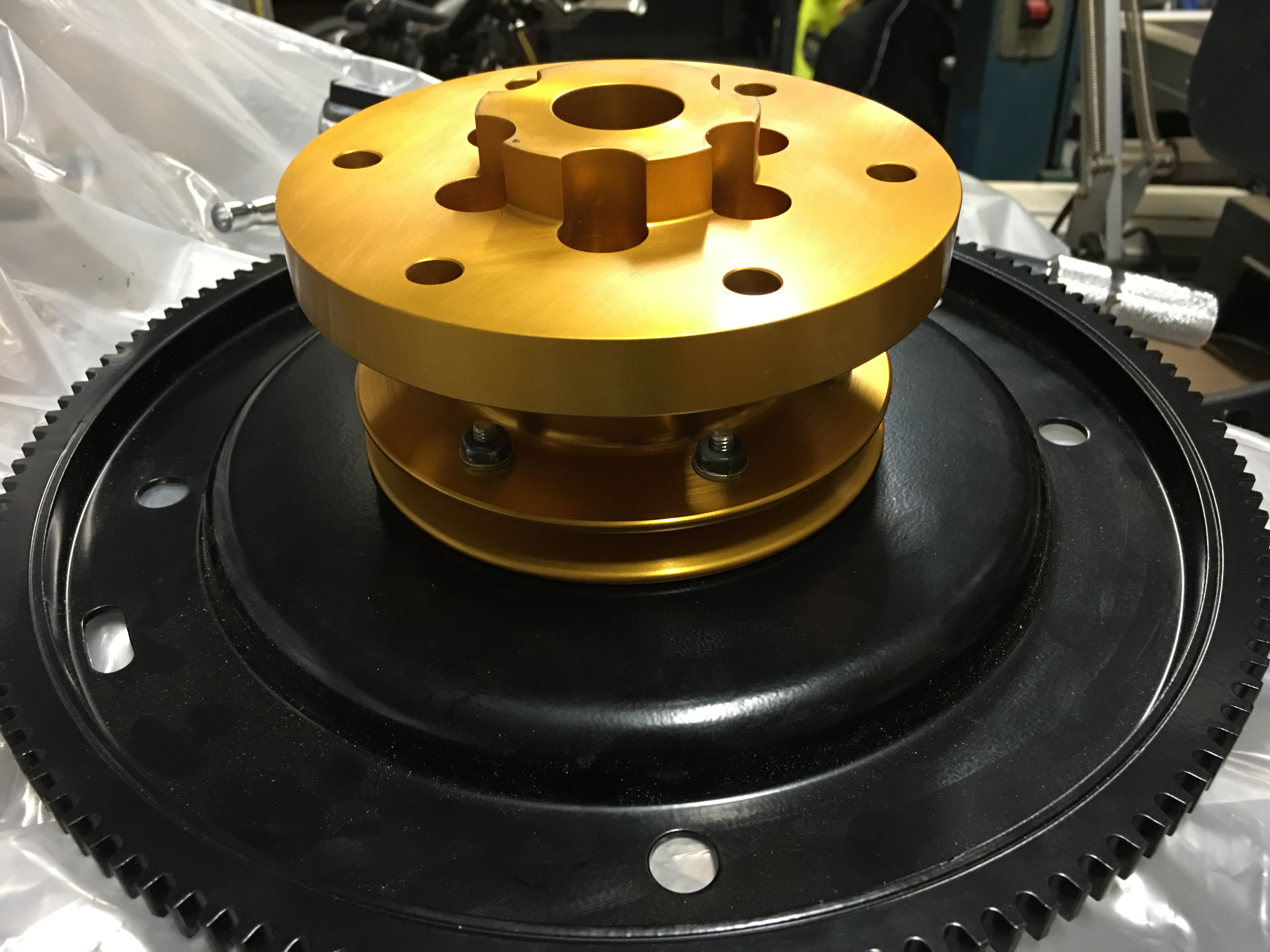
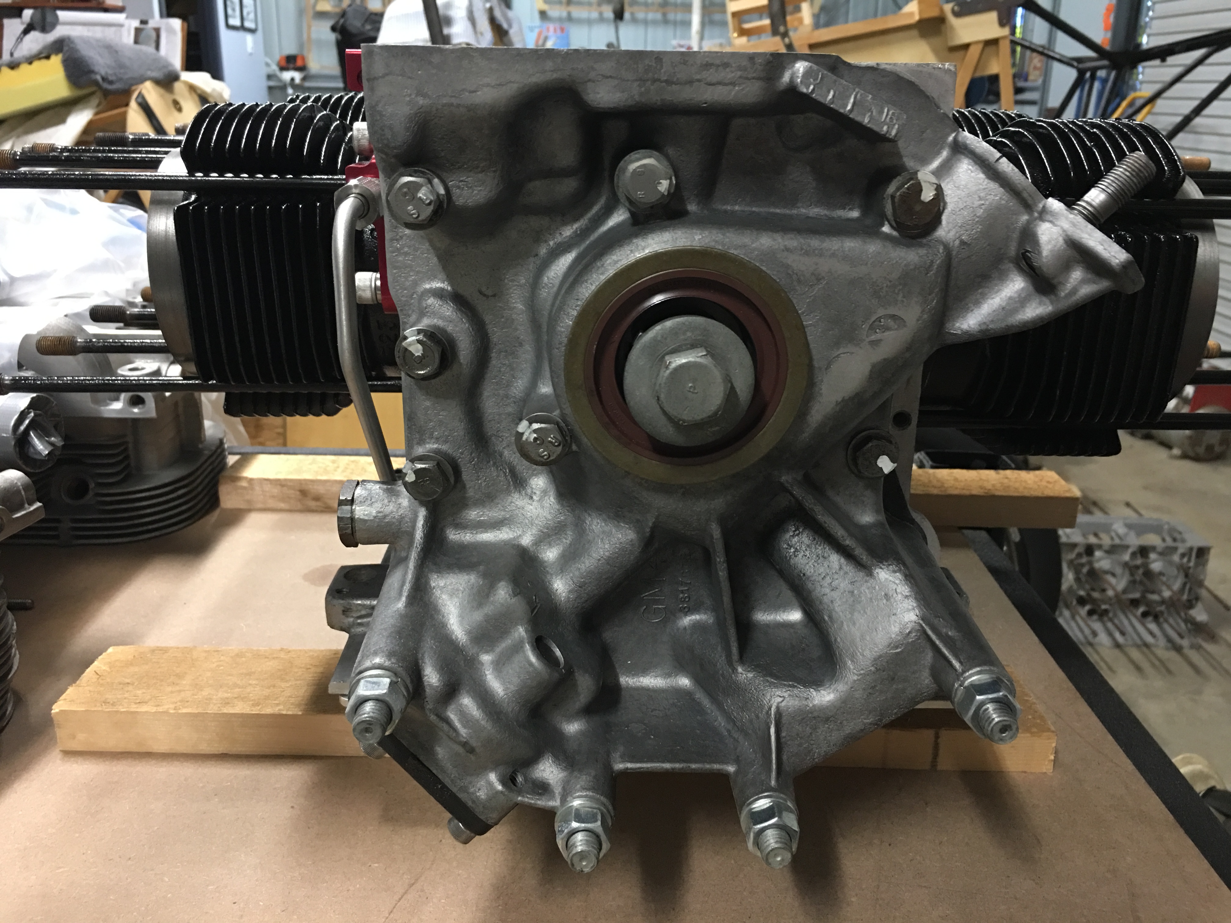
Gold hub secured to starter gear and safety shaft and hybrid studs fitted.
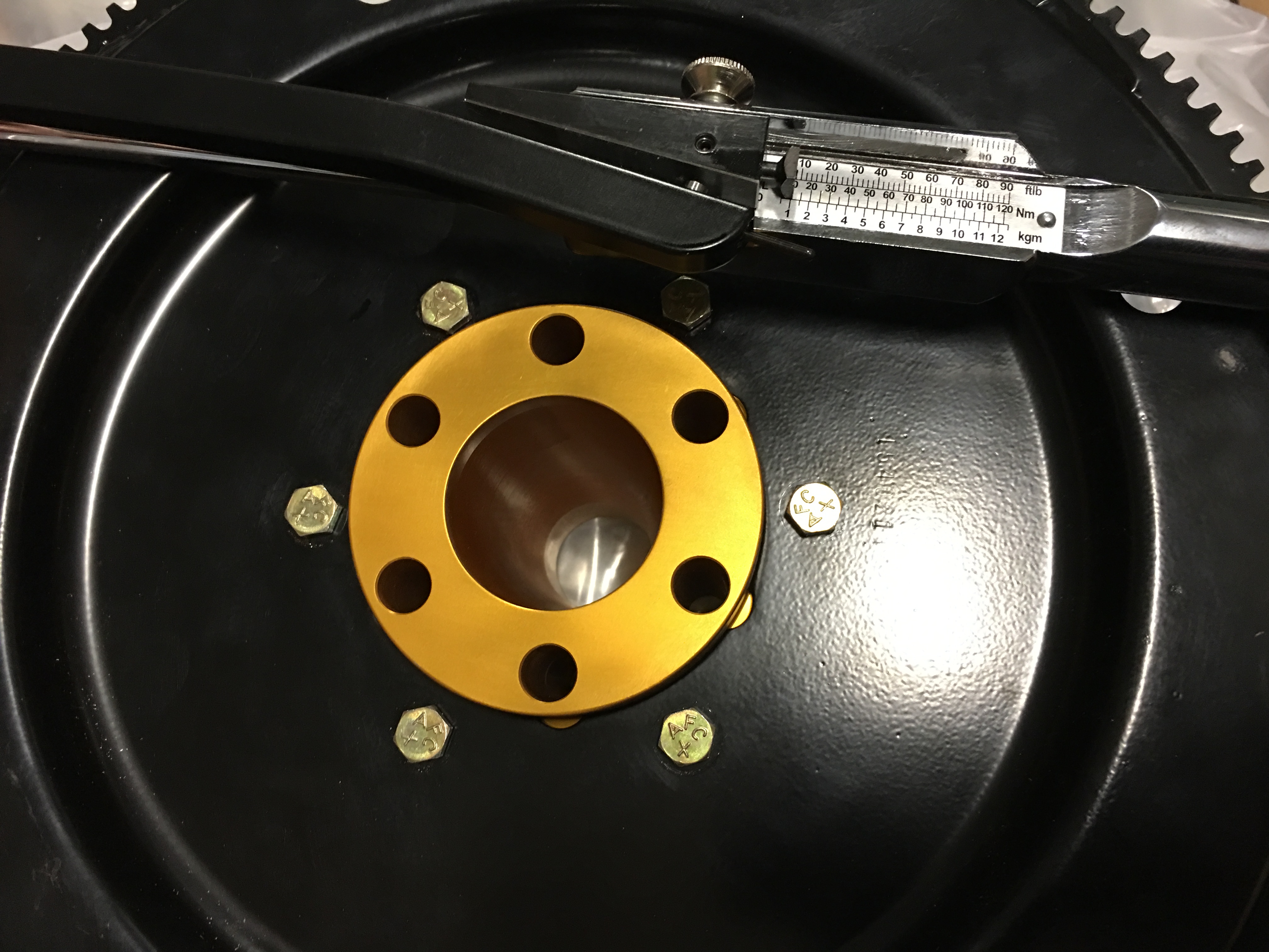
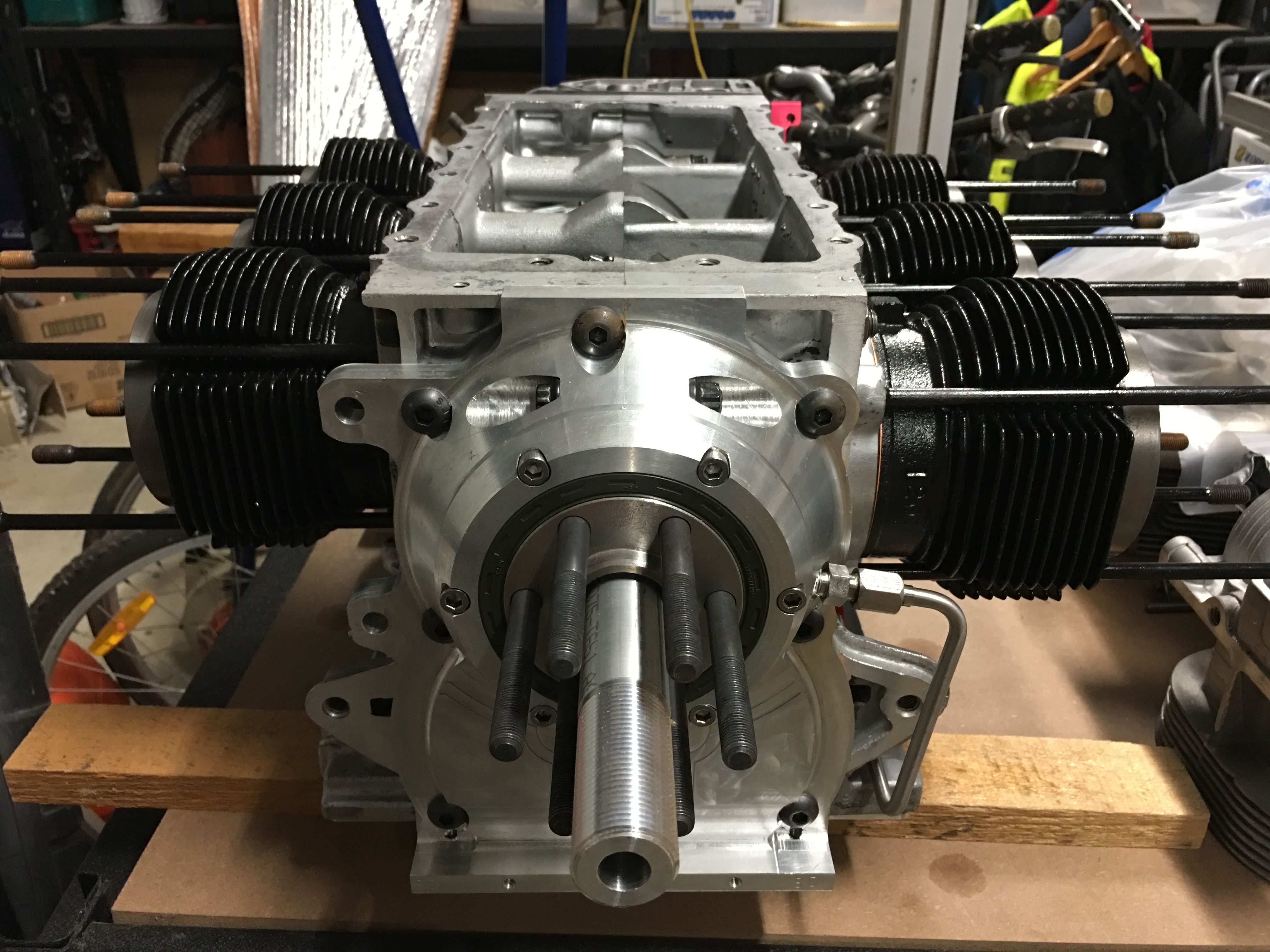
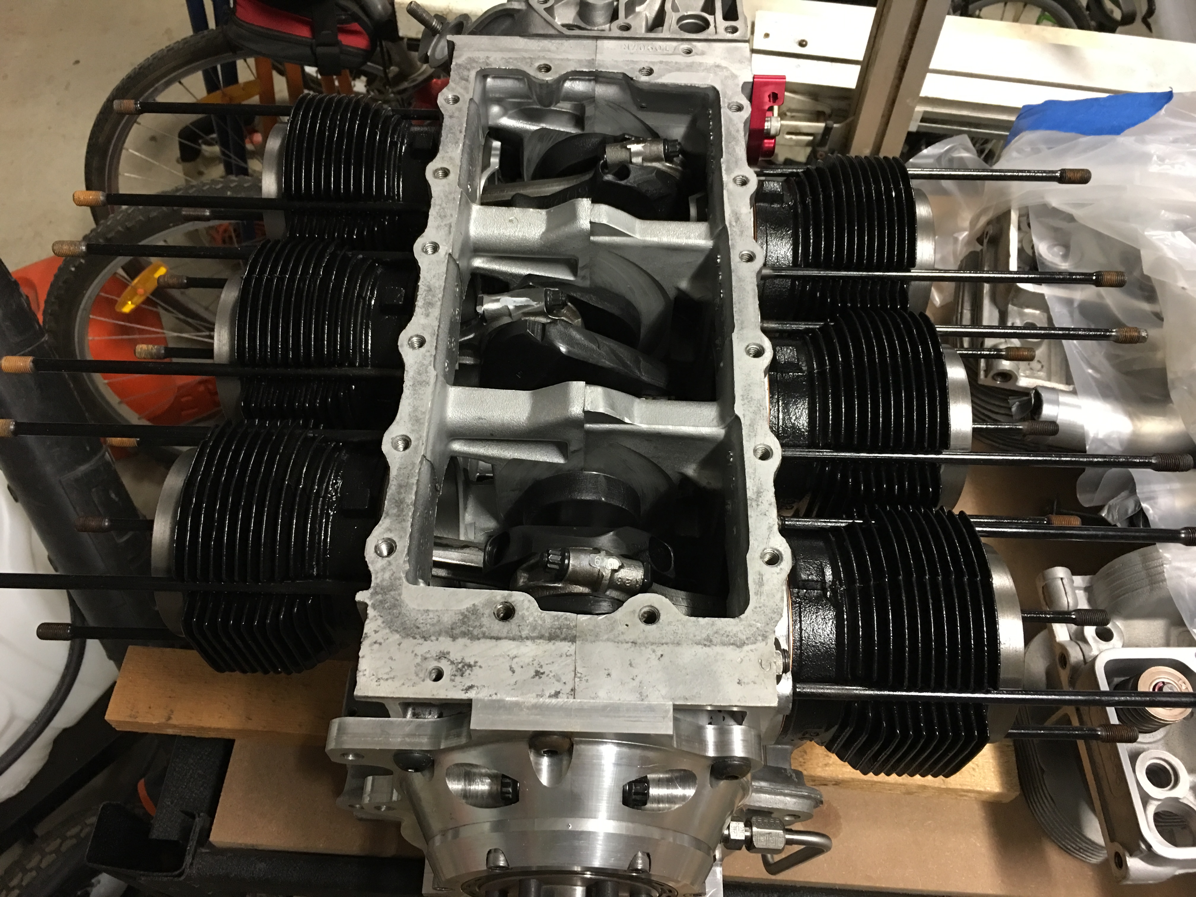

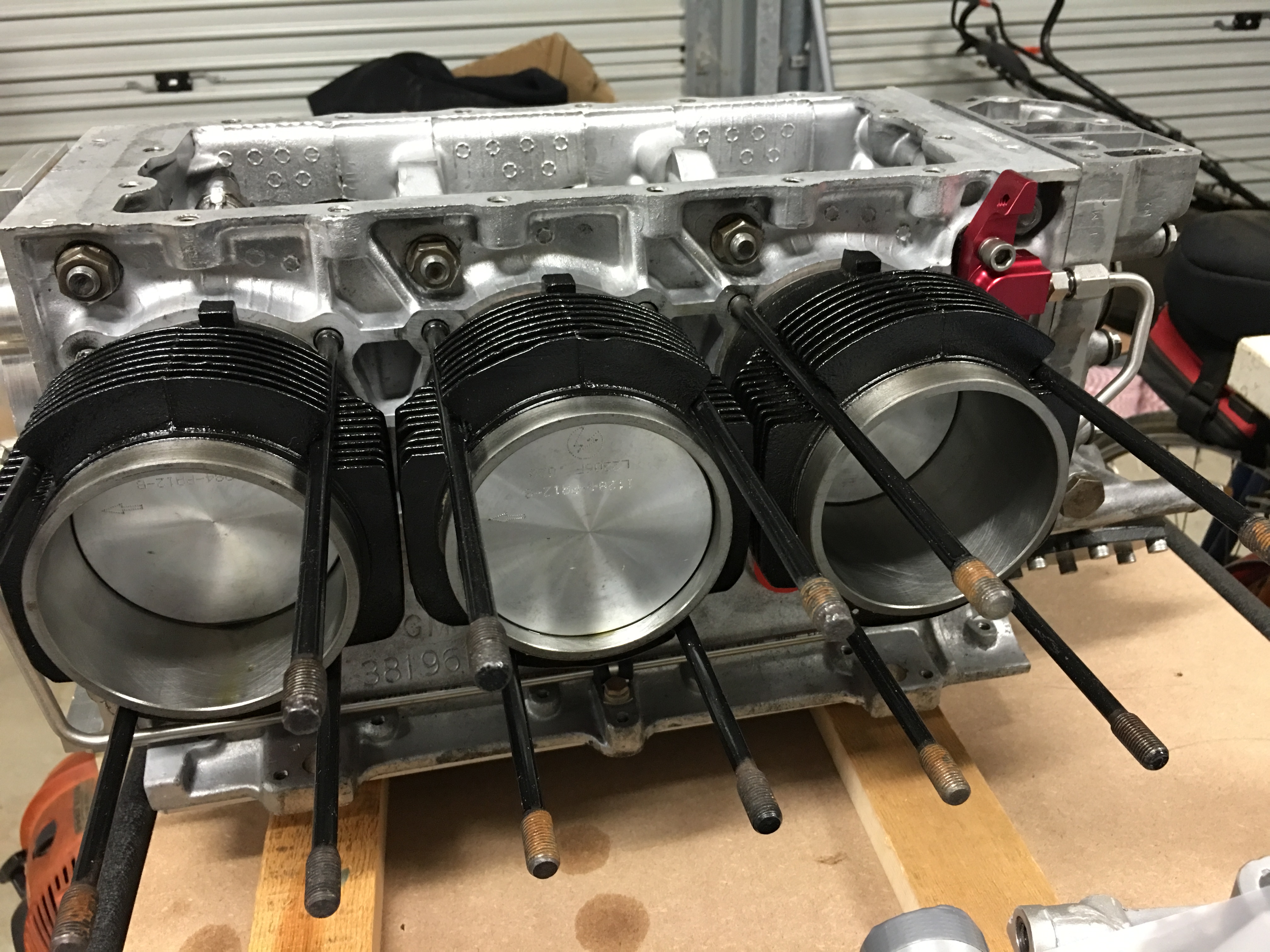

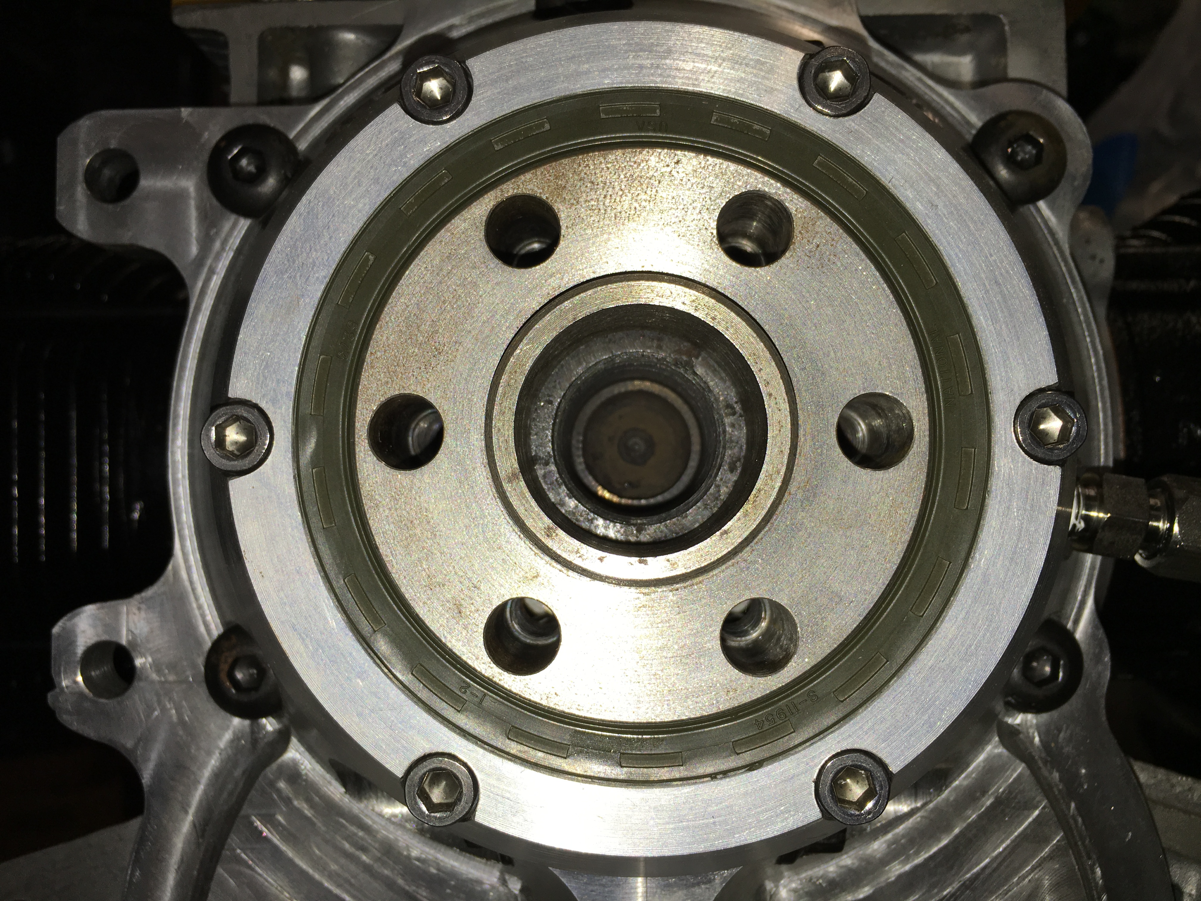


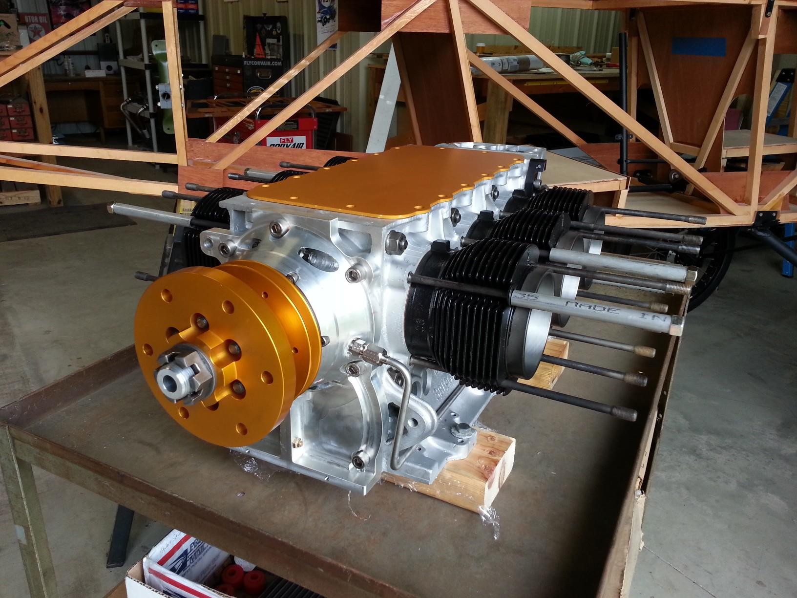
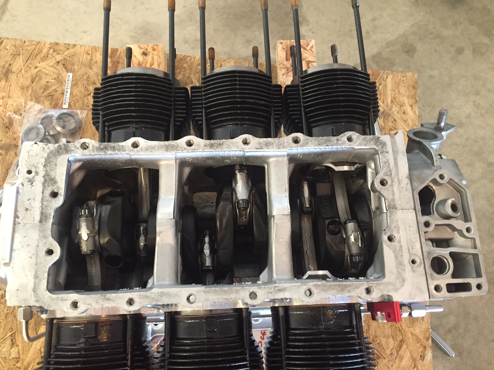
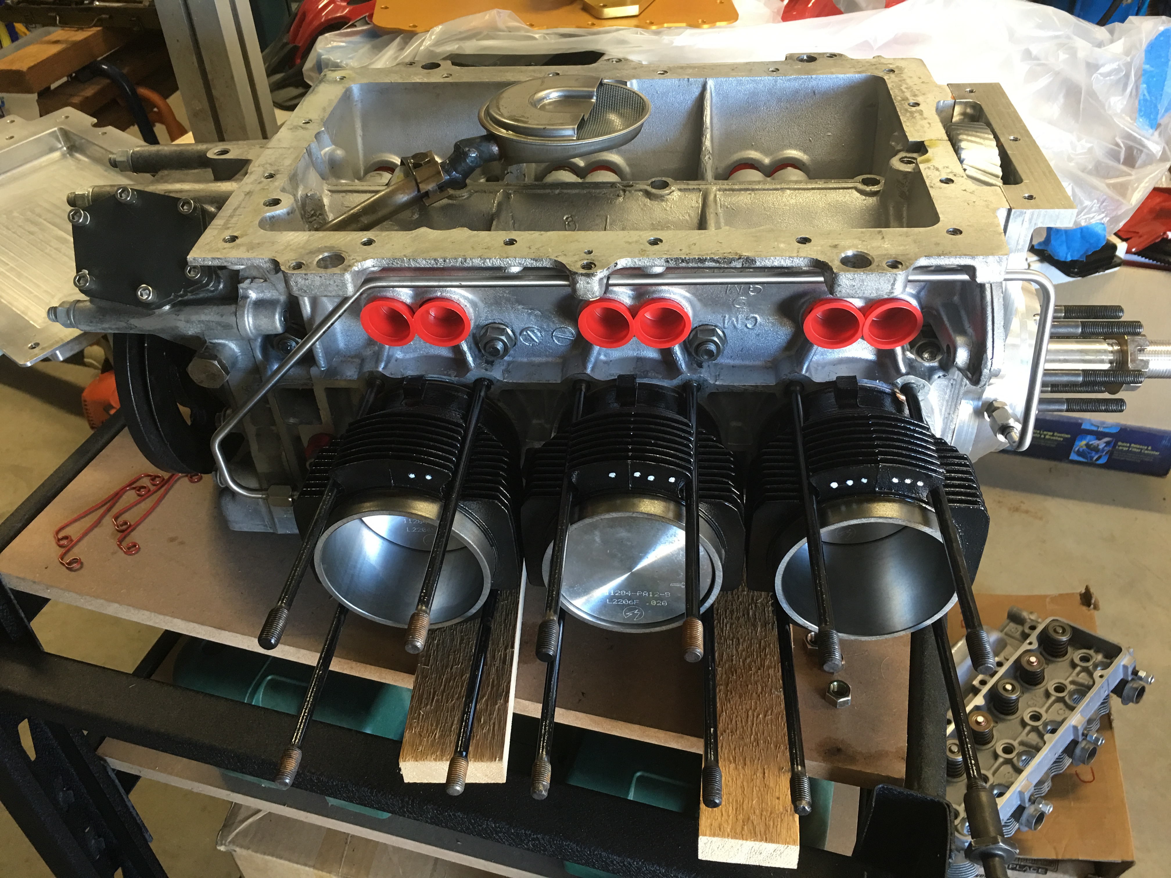
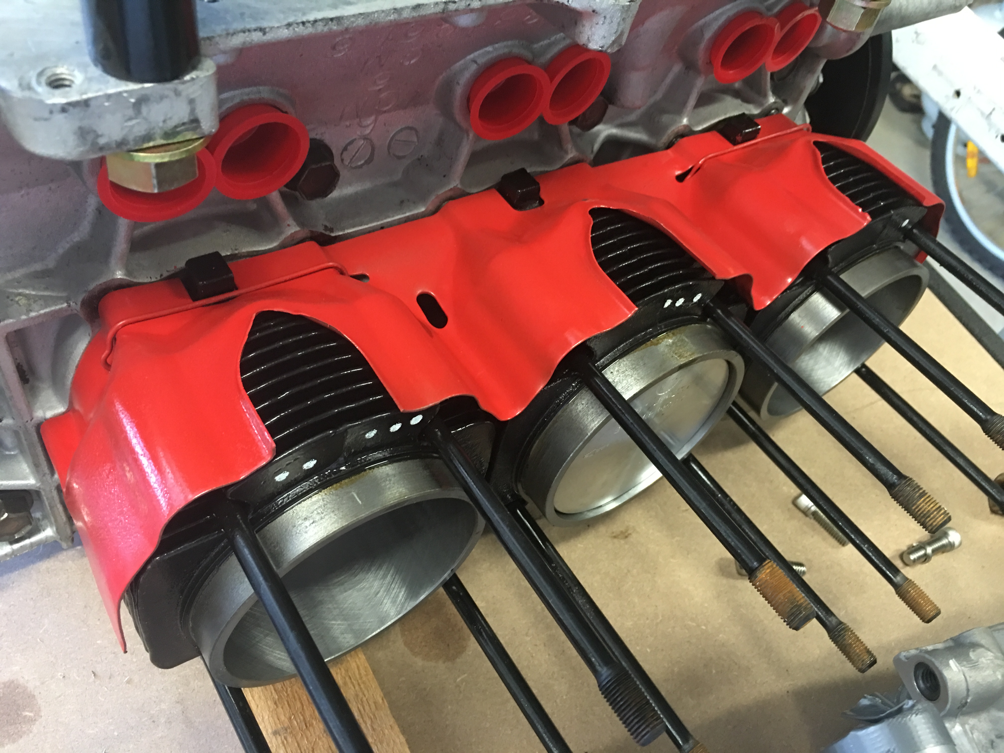
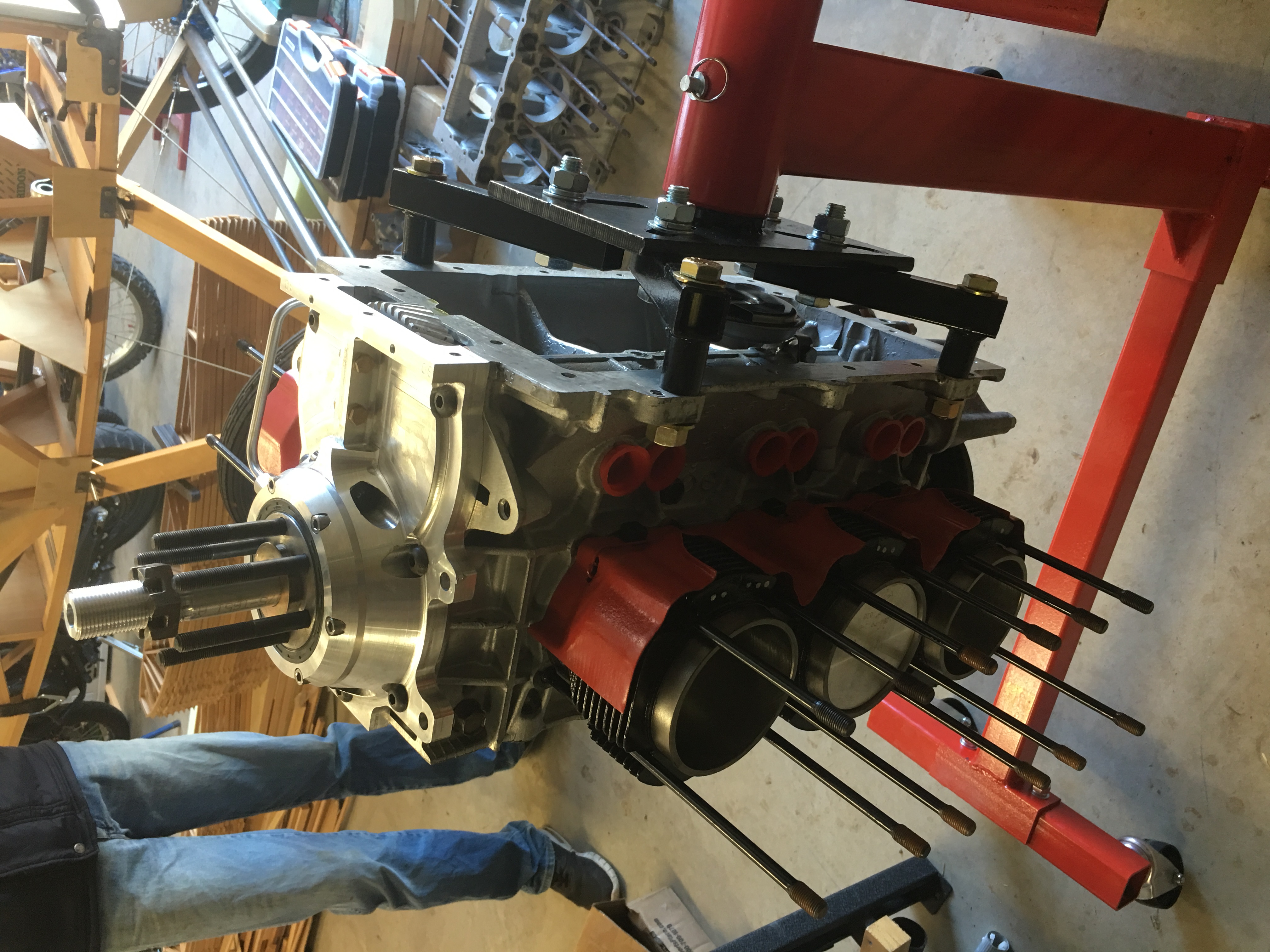
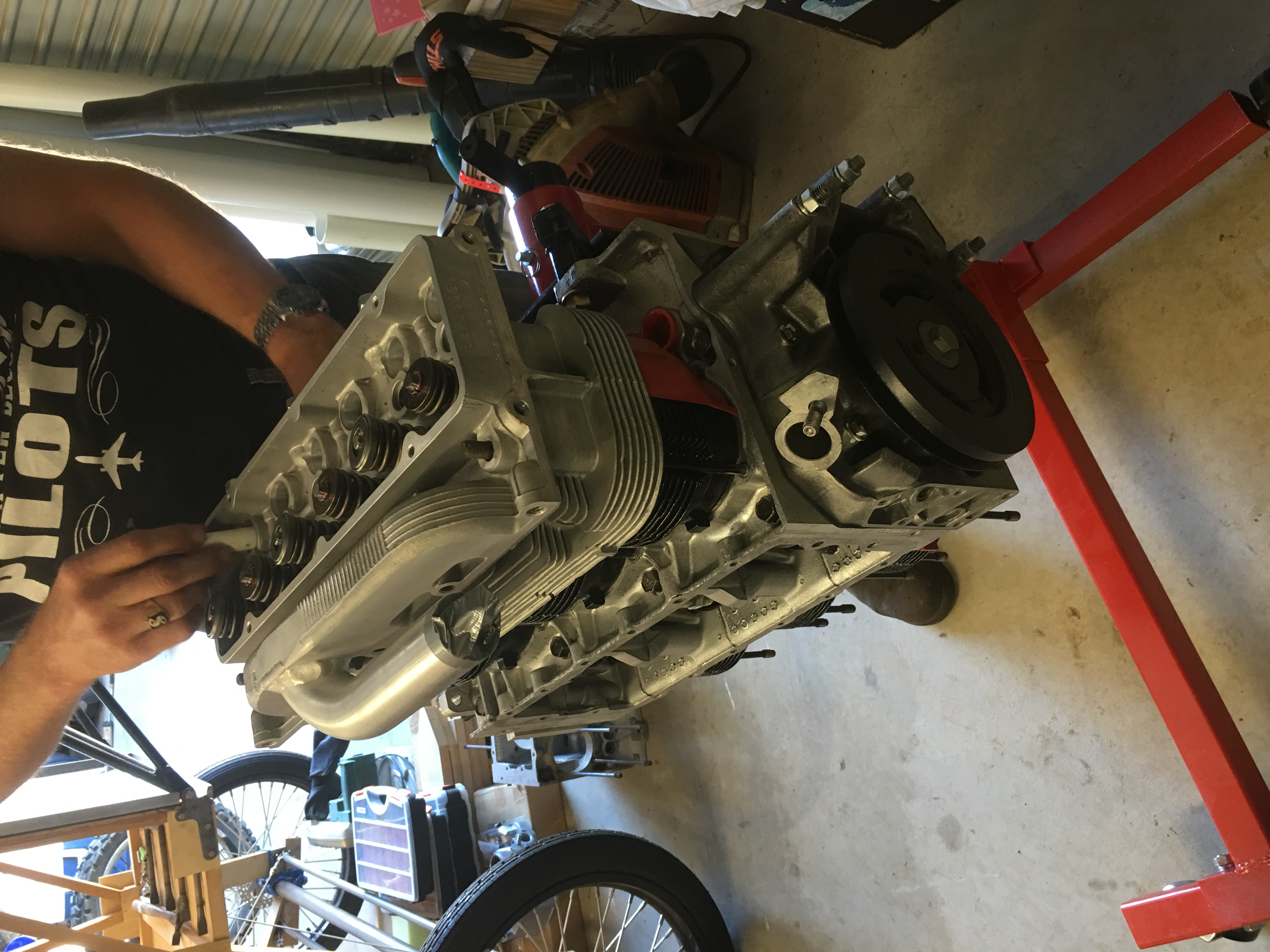
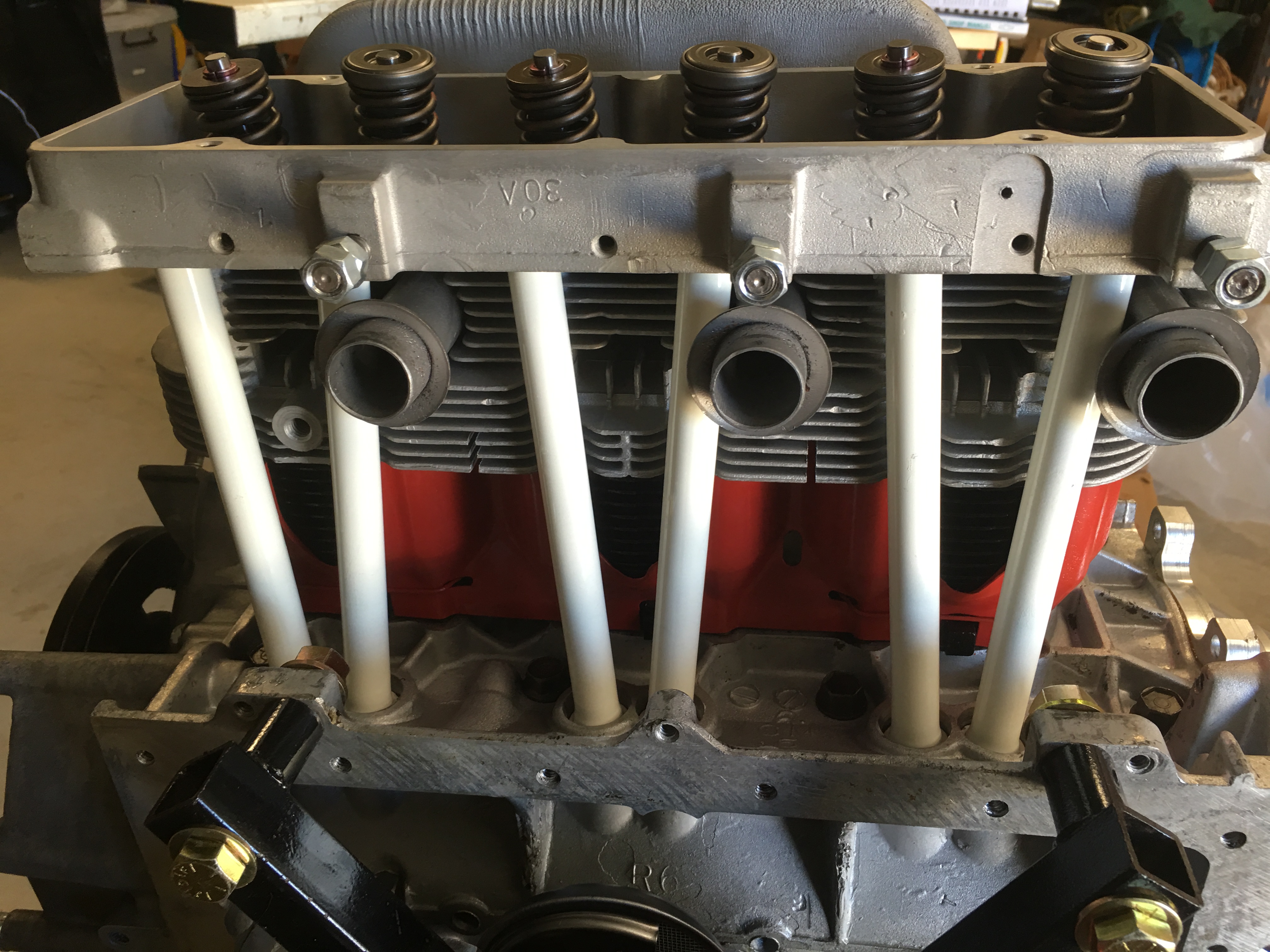
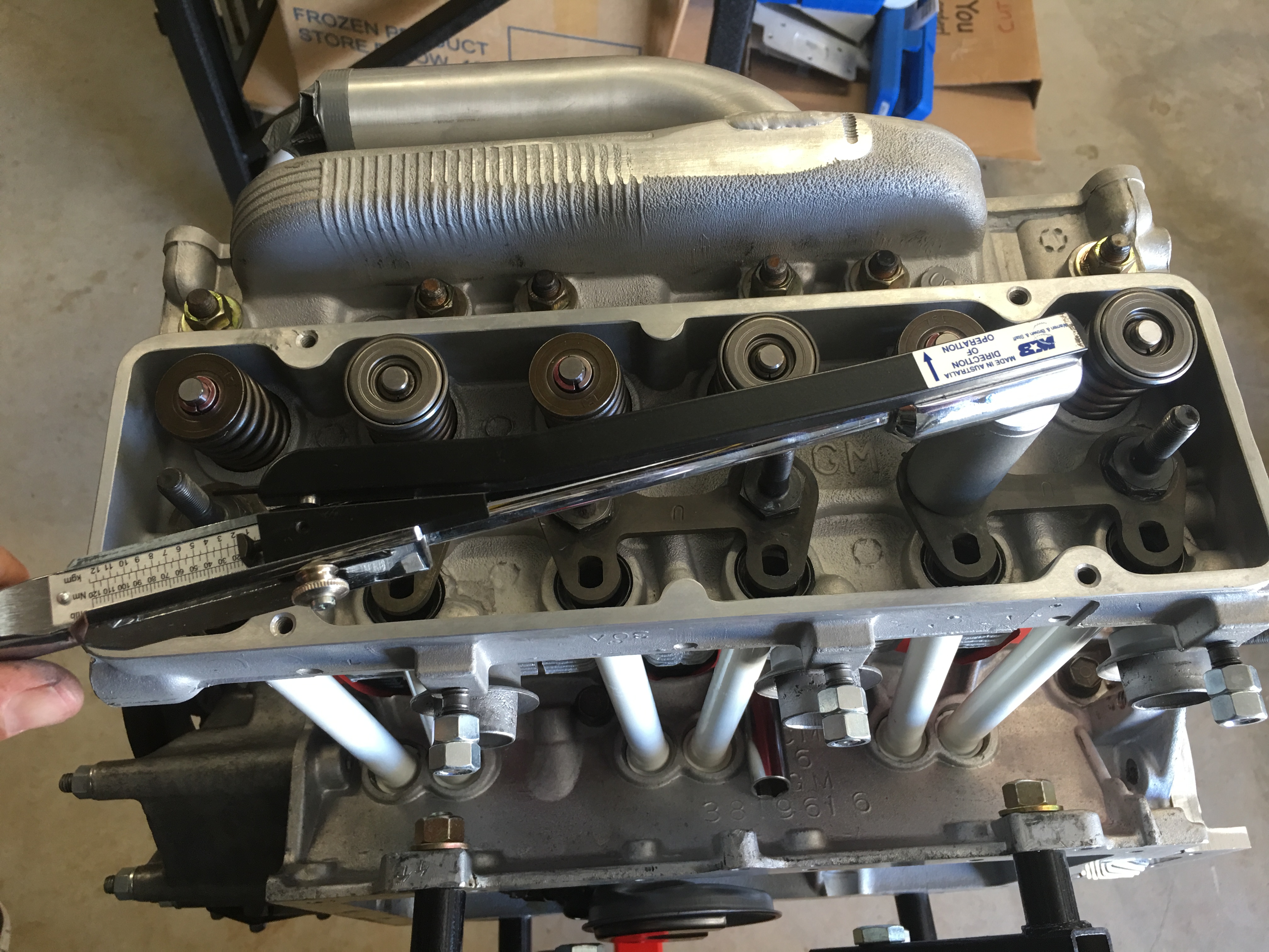
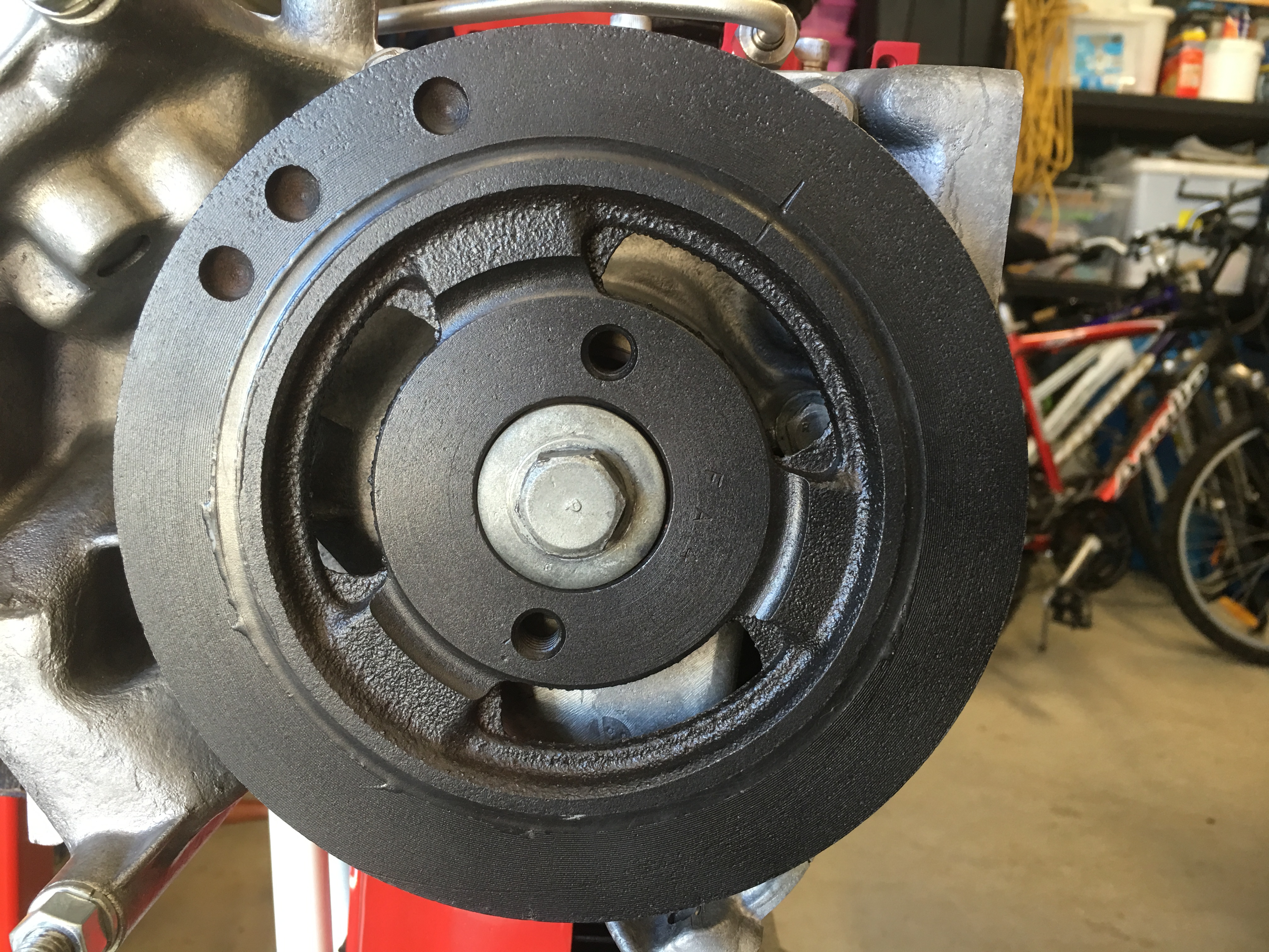
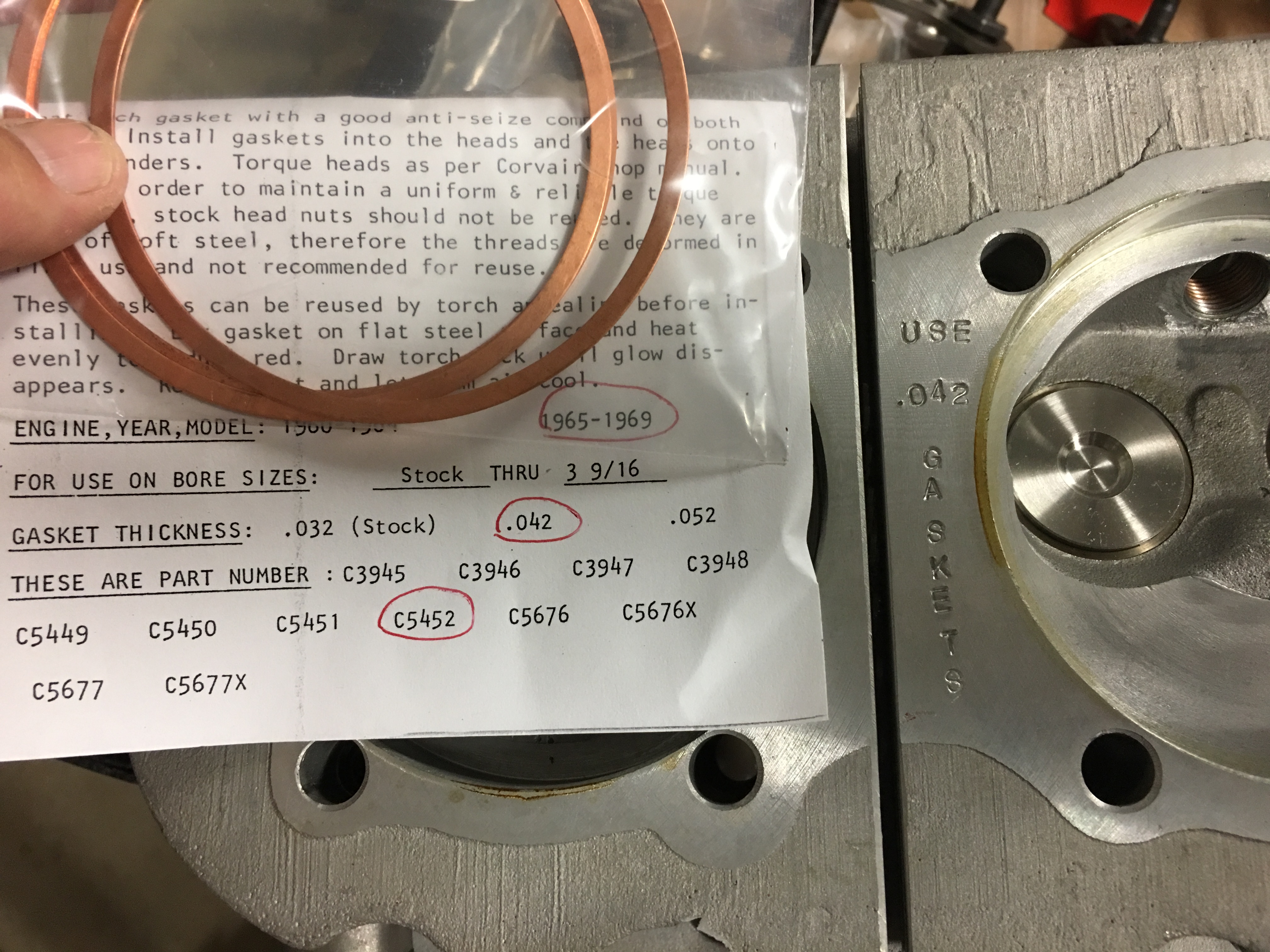
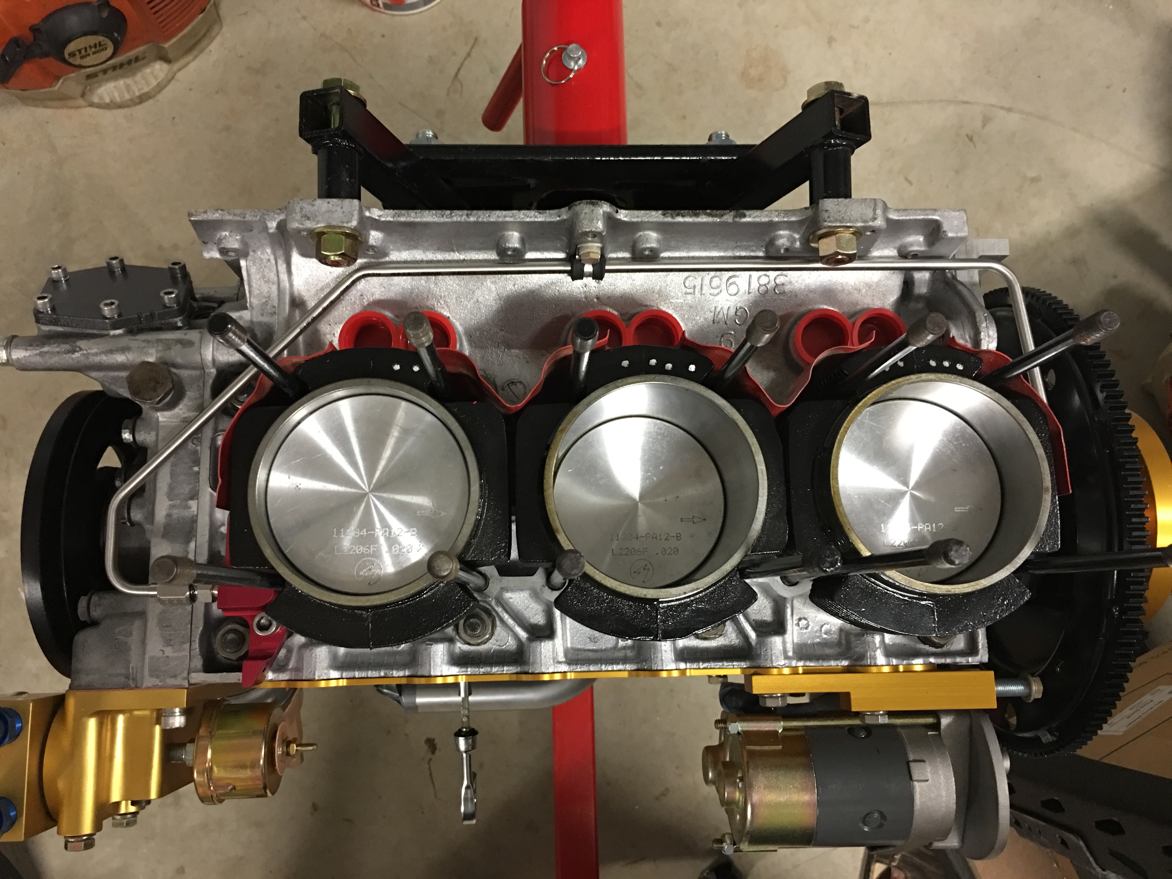
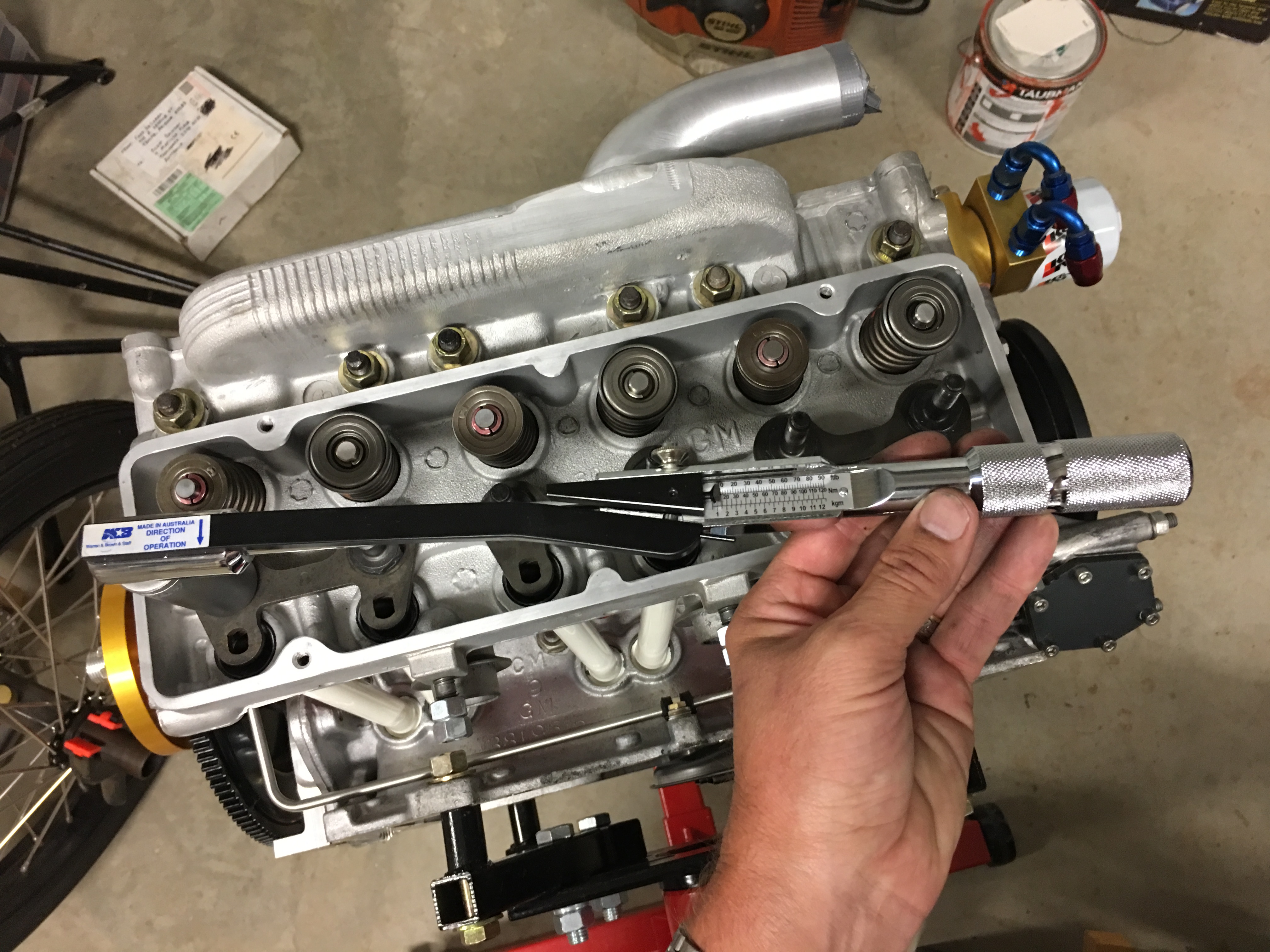
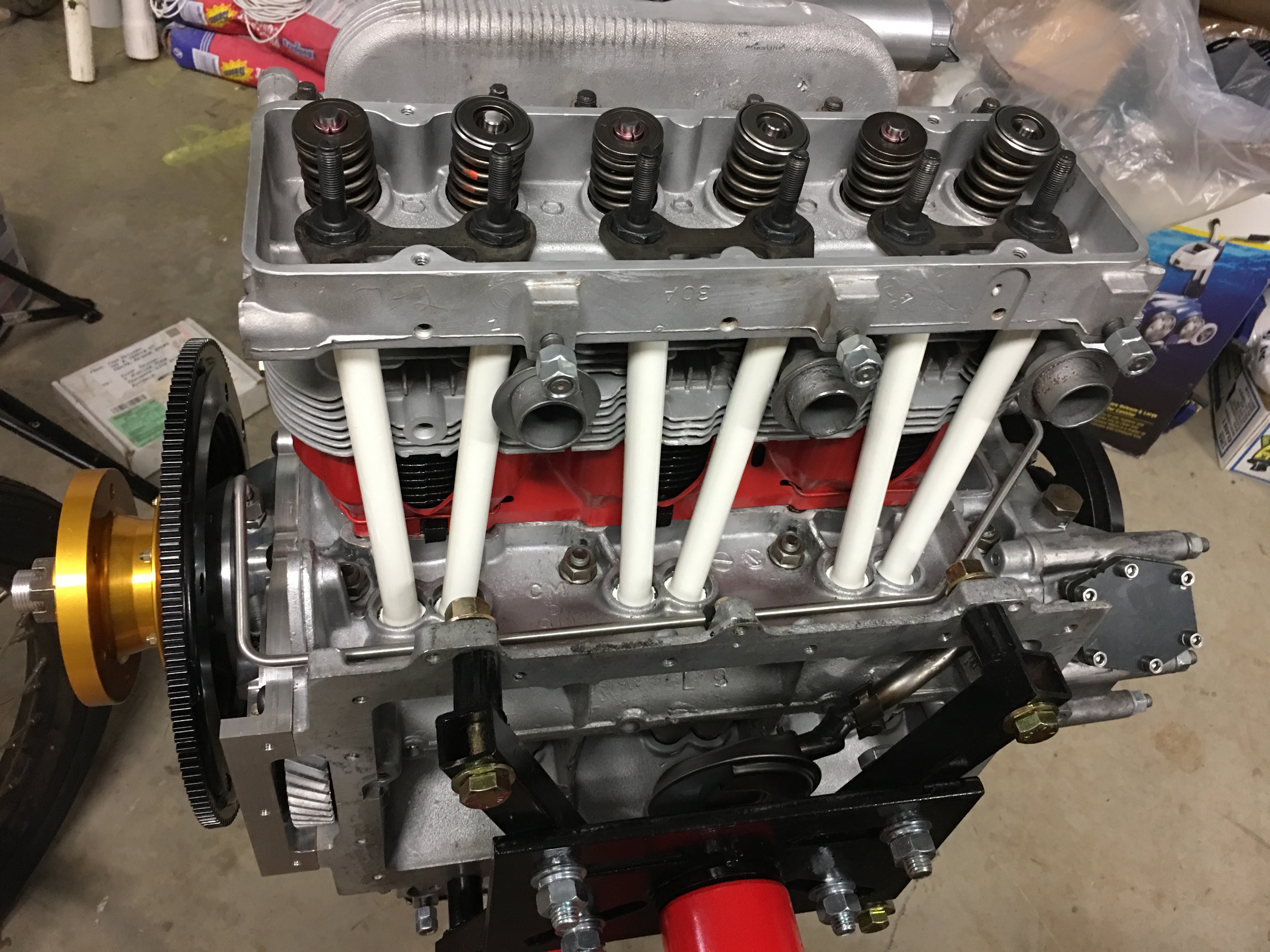
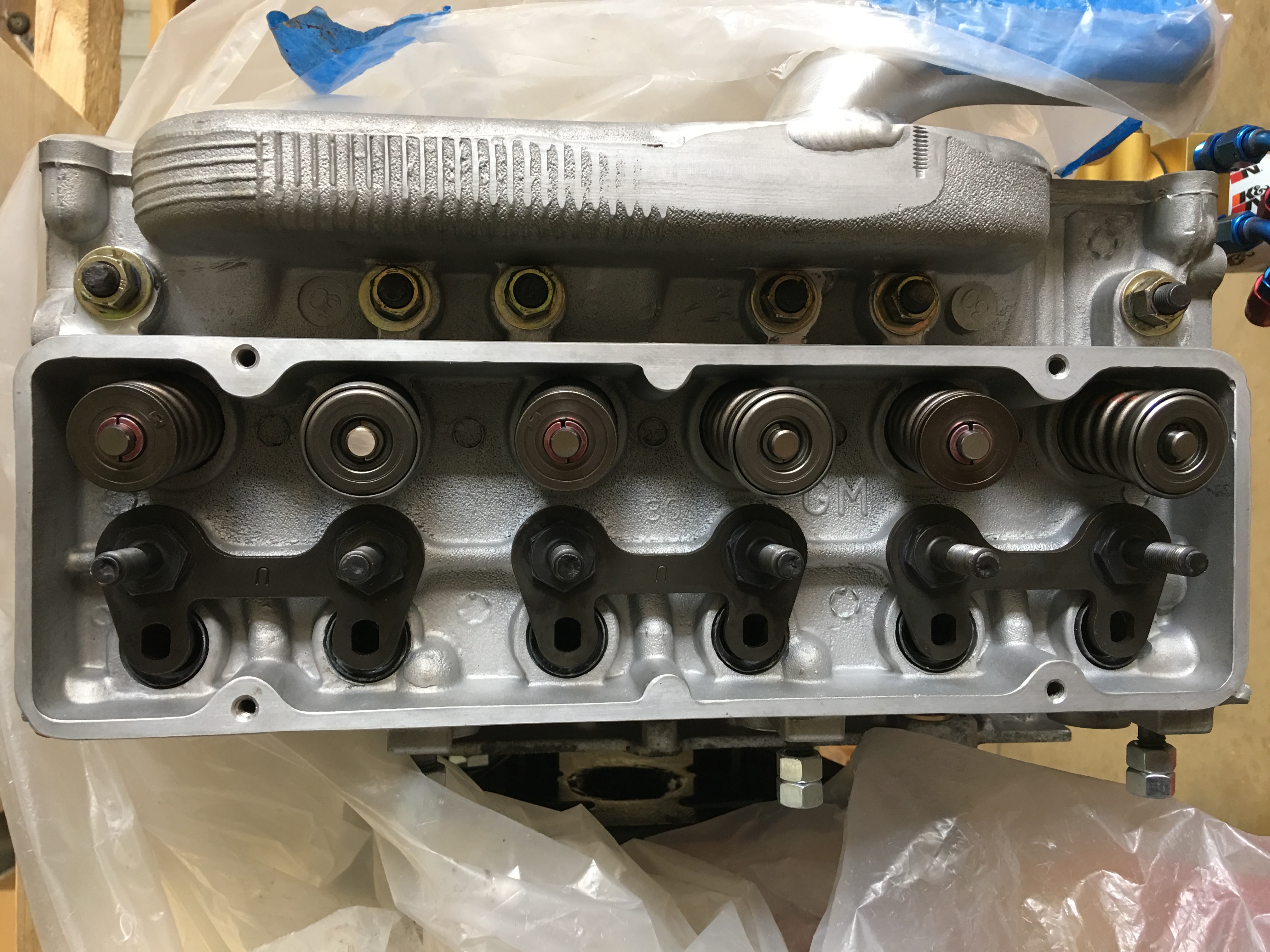
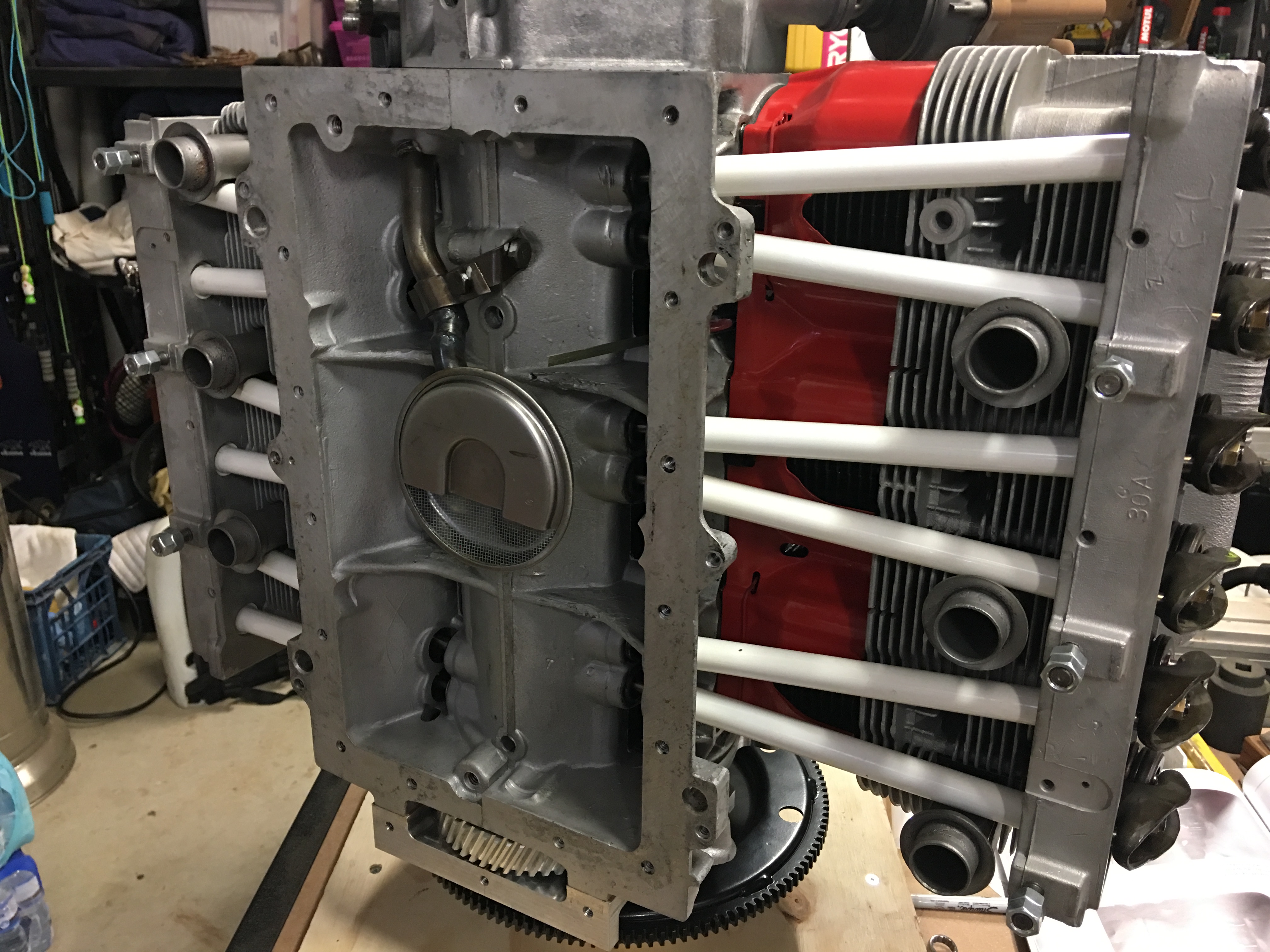
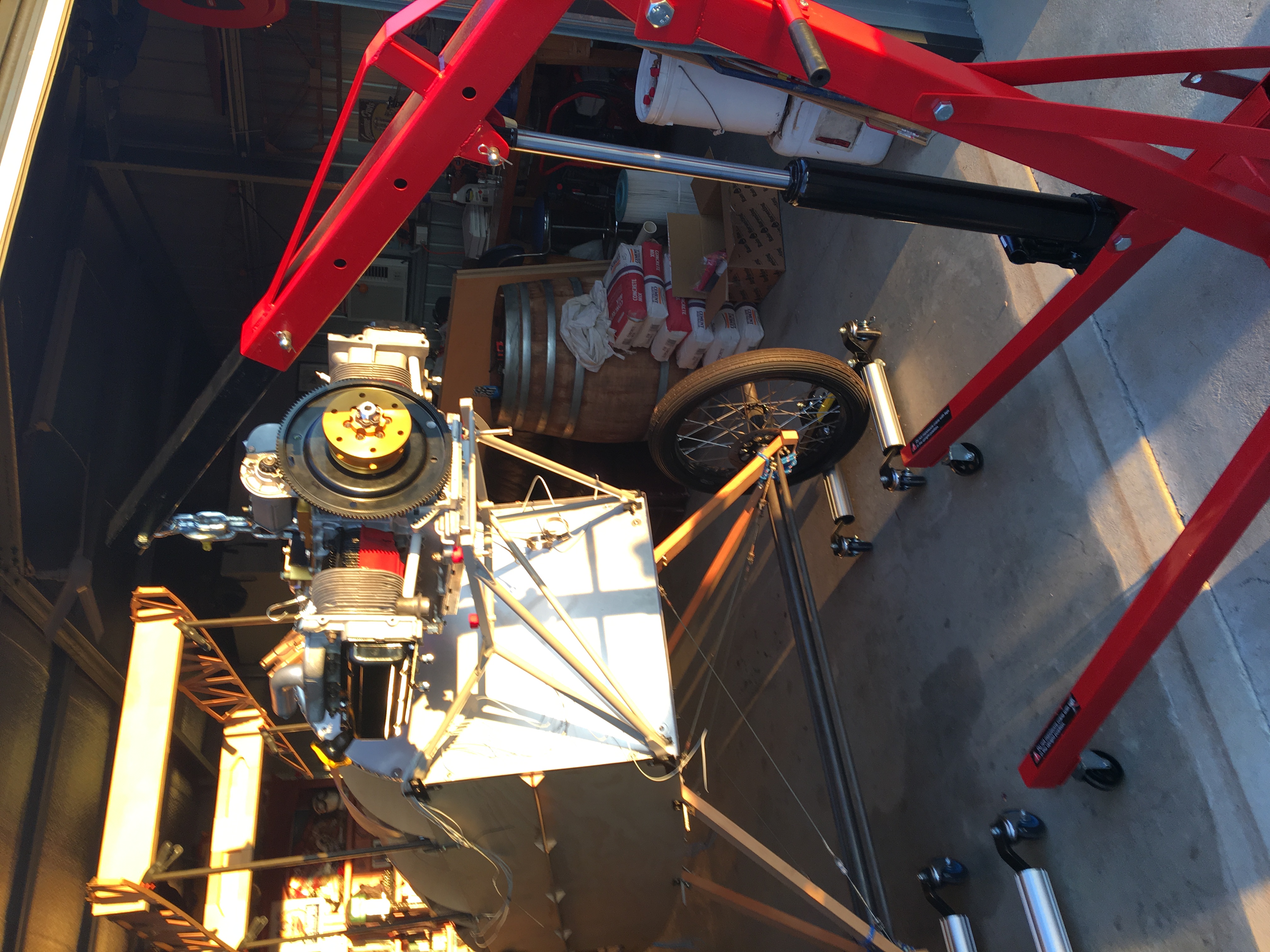
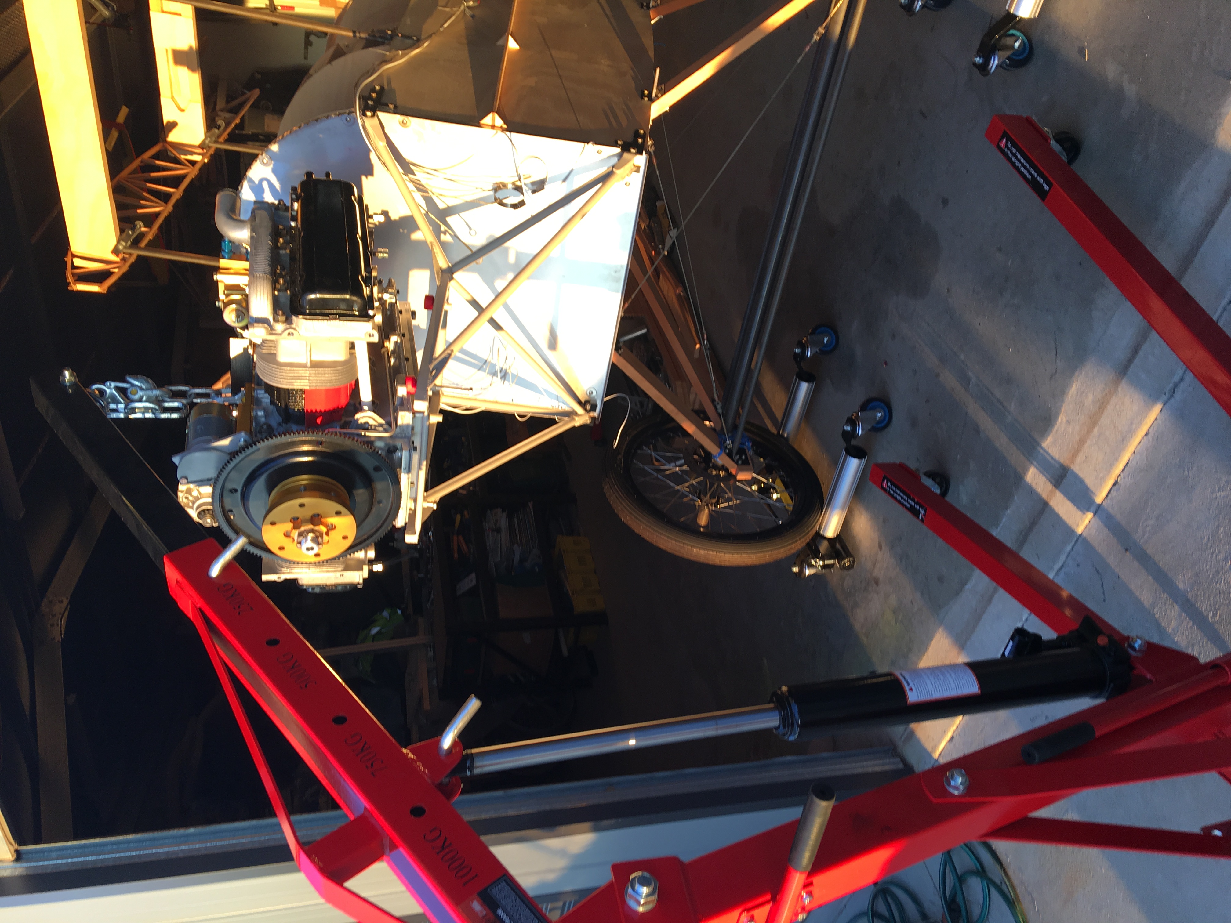
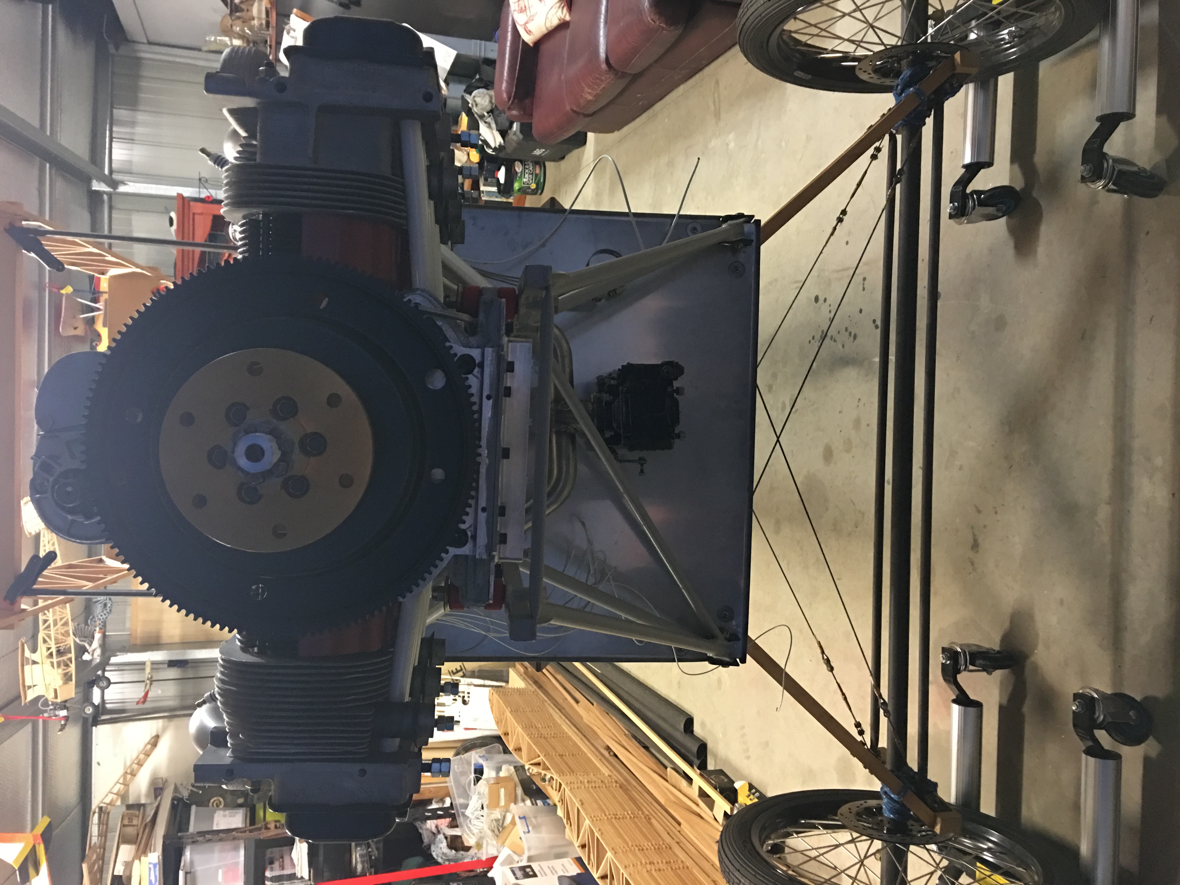
Engine mounted to stand. 1-3-5 cylinder side head torqued down with pushrod tubes and balancer fitted.


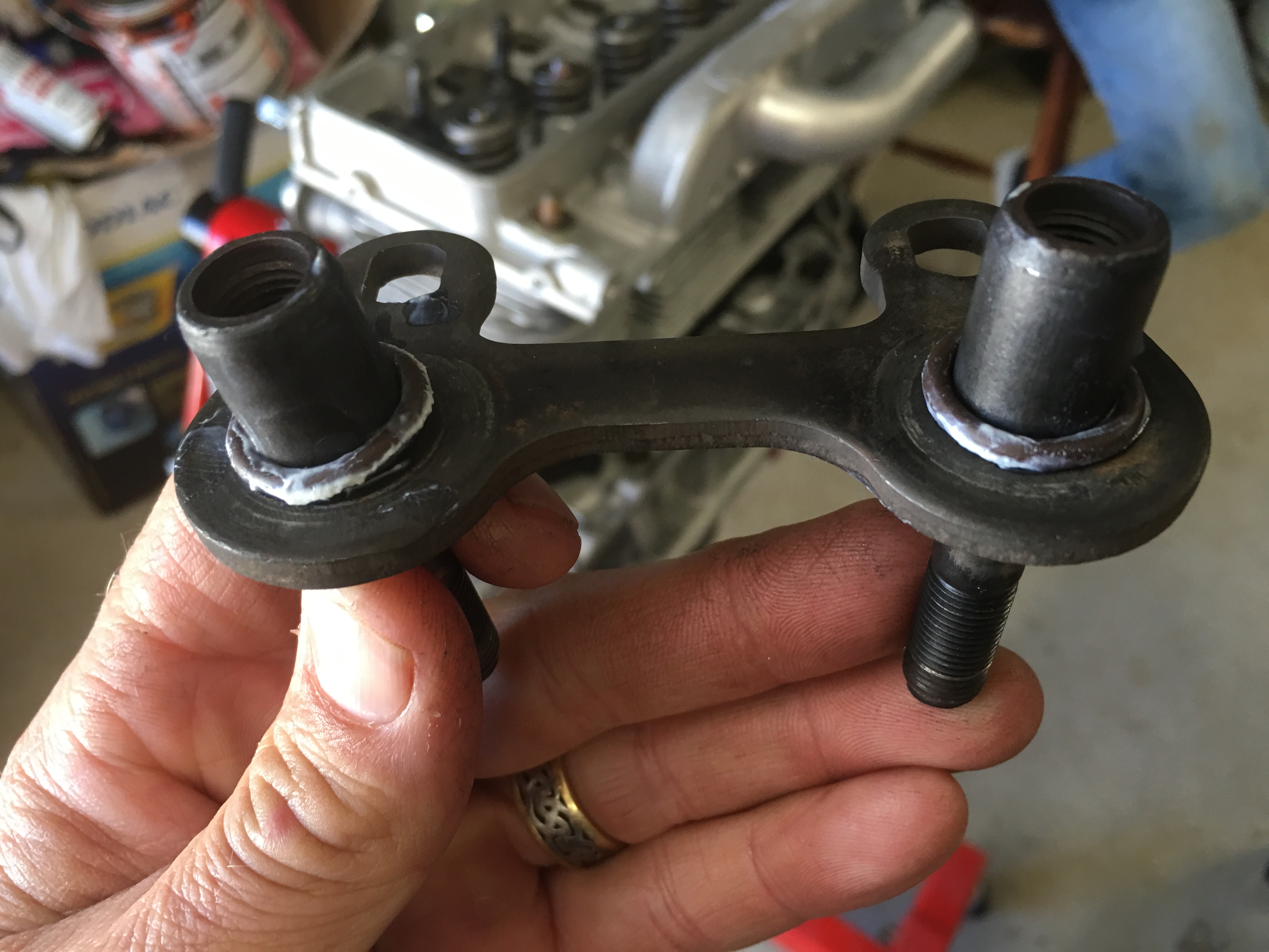


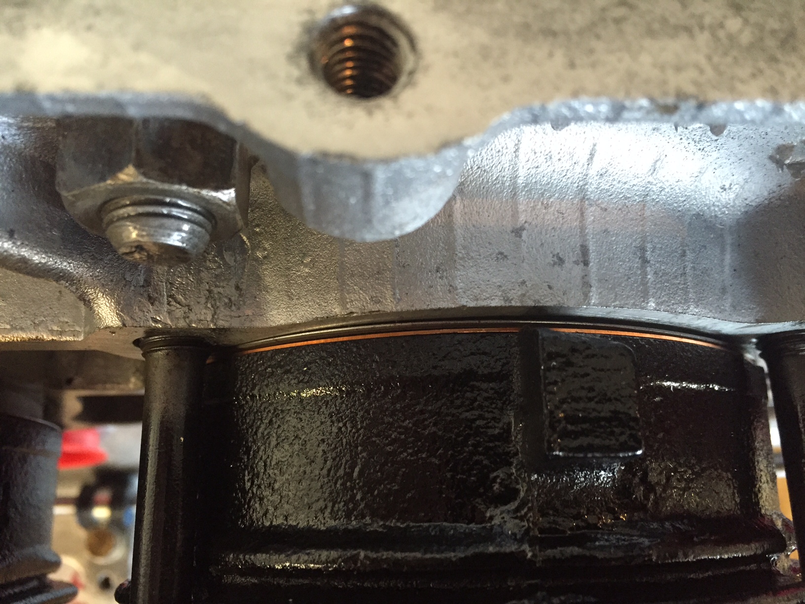
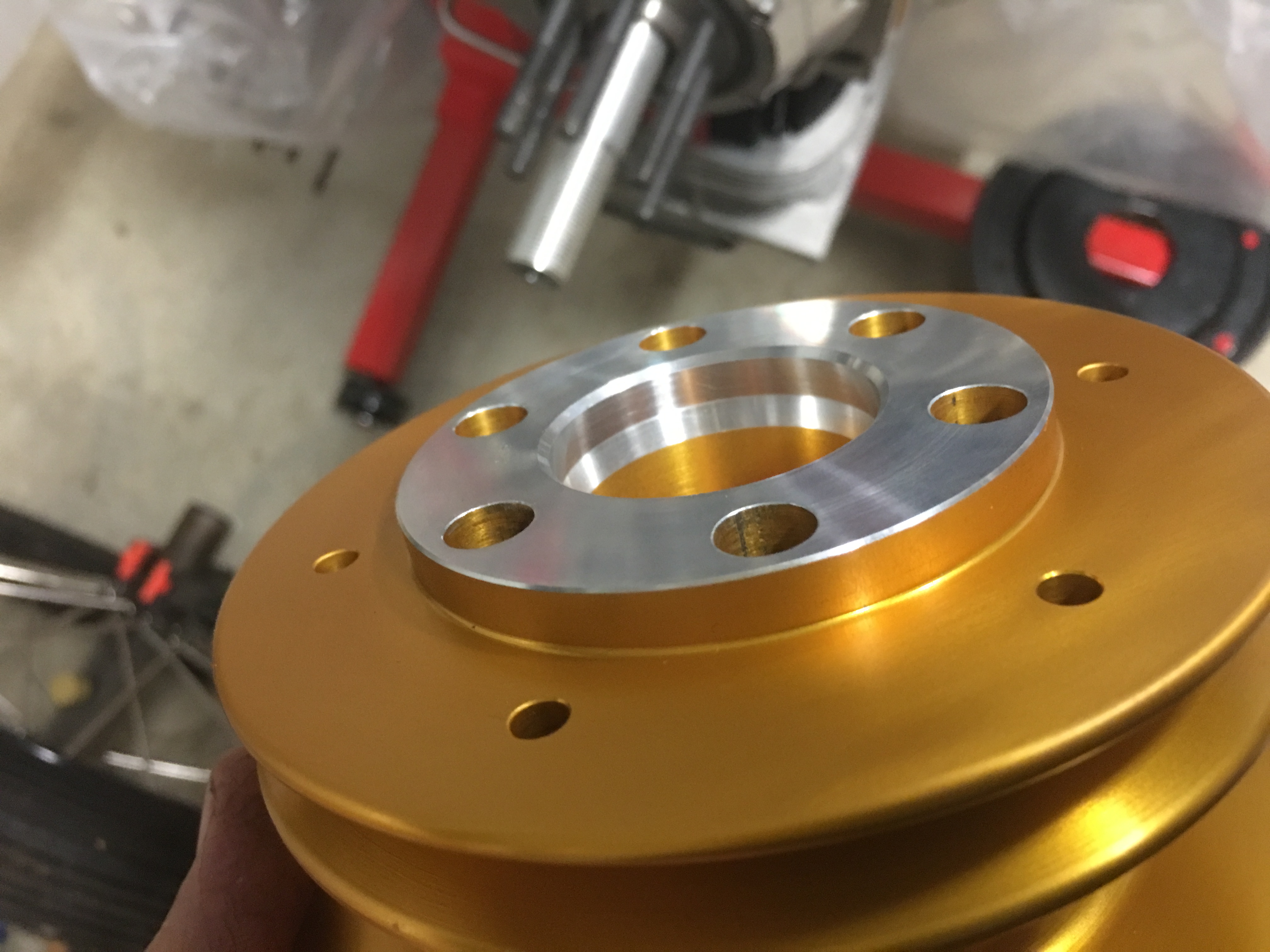
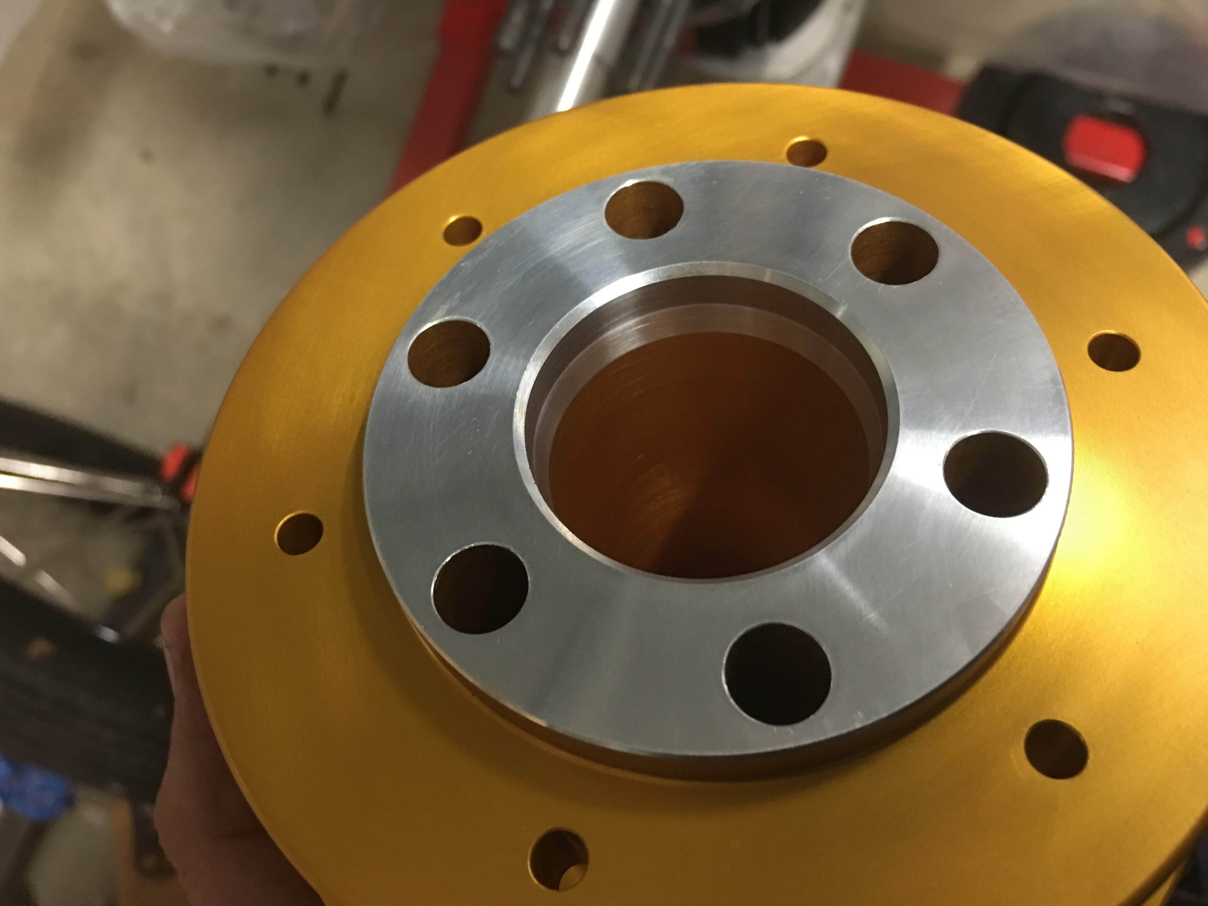
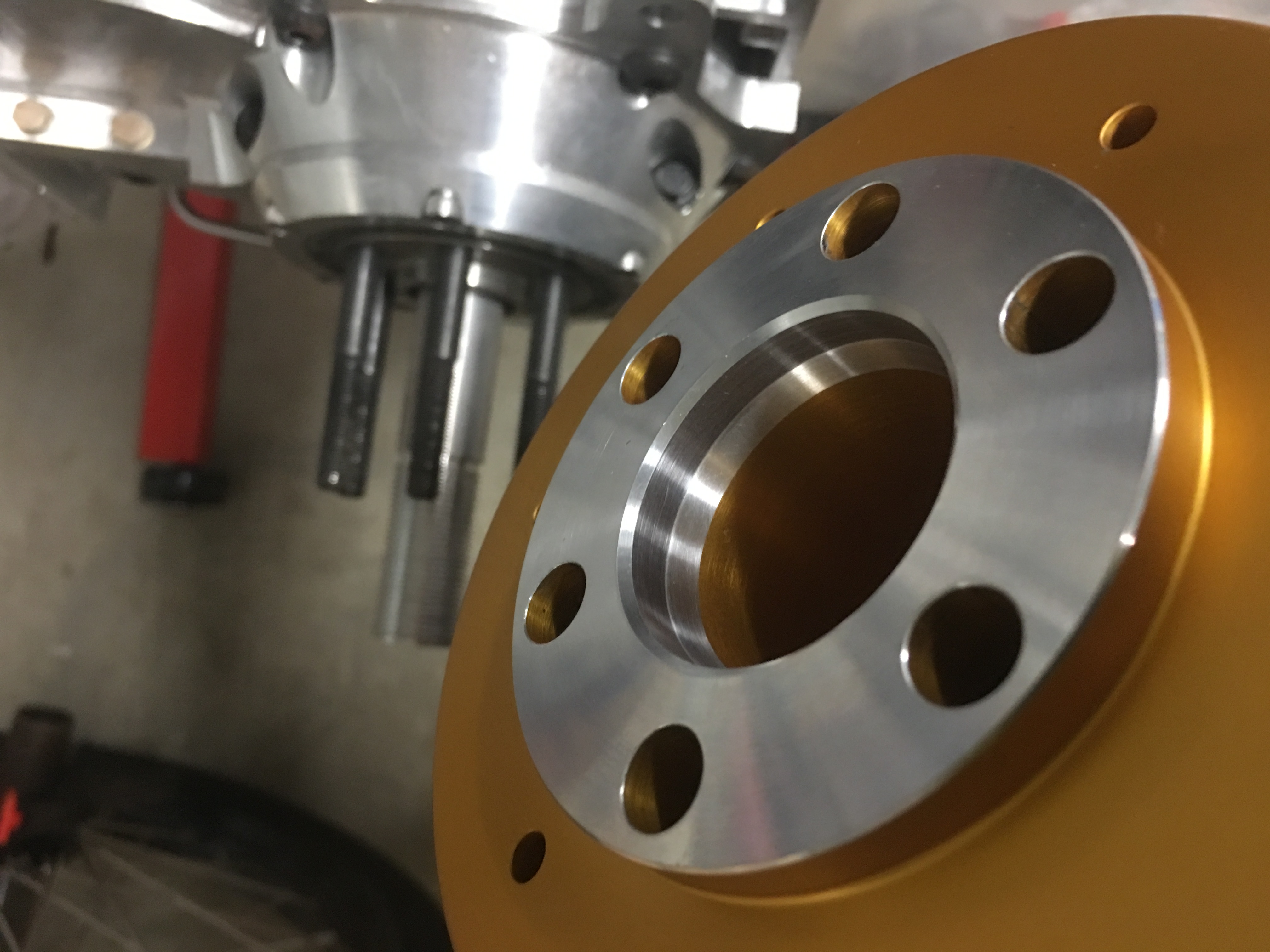
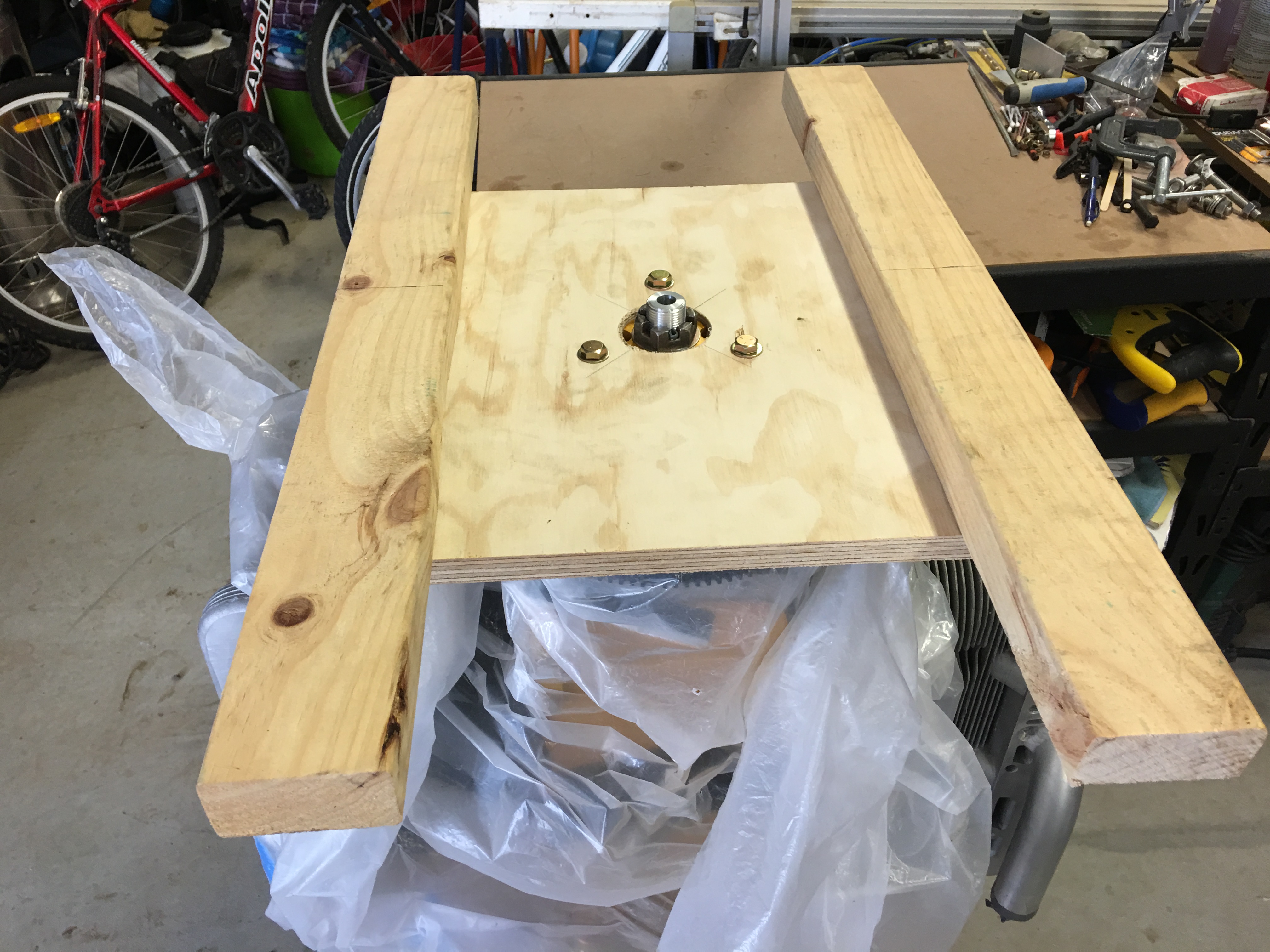
When using Roys 5th bearing, there needs to be a modification to the rear surface of the gold hub. If this is not done, there wont be enough thread available on the hybrid studs to secure the nuts. This is what it looks like after the modification.

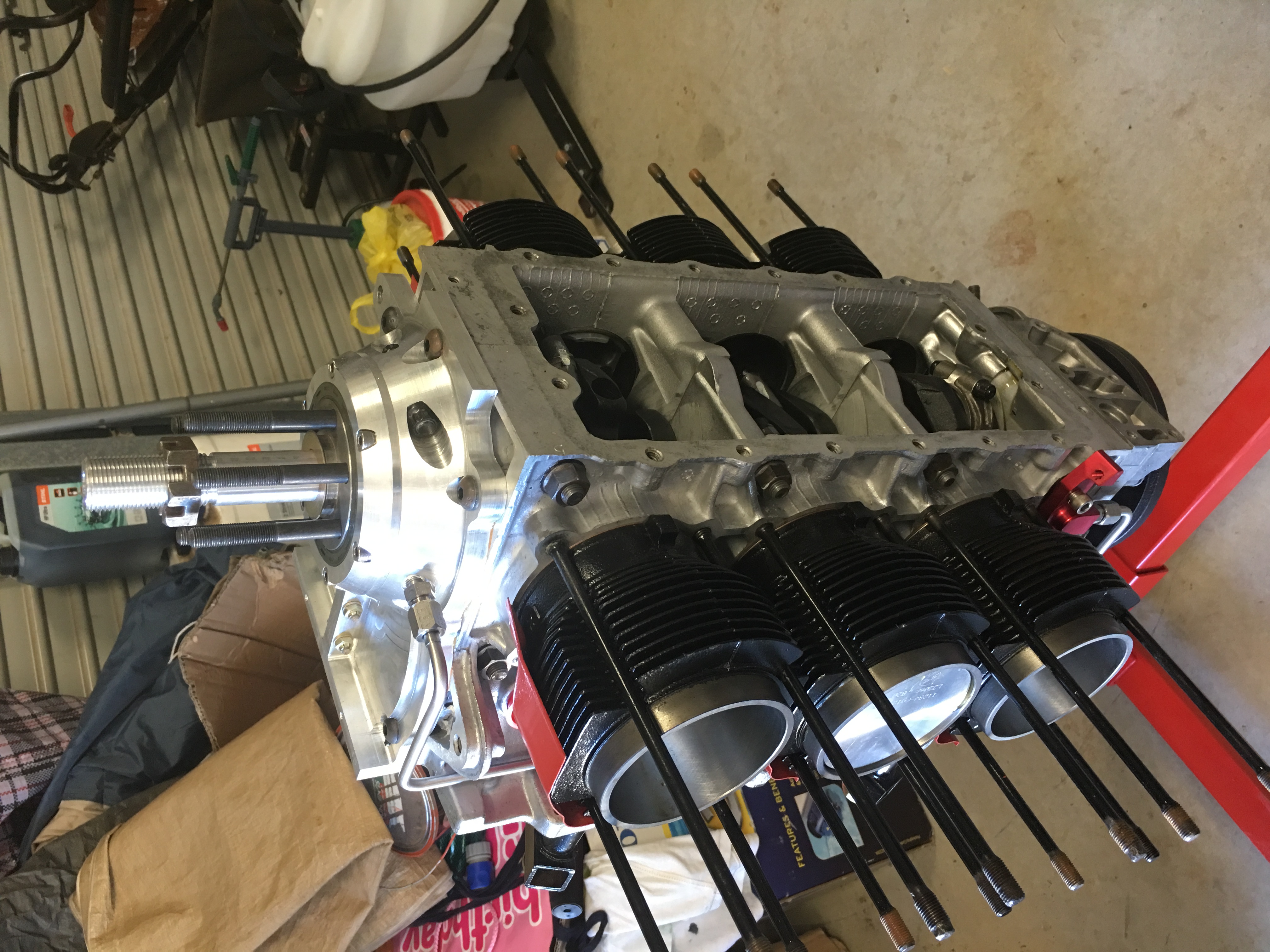
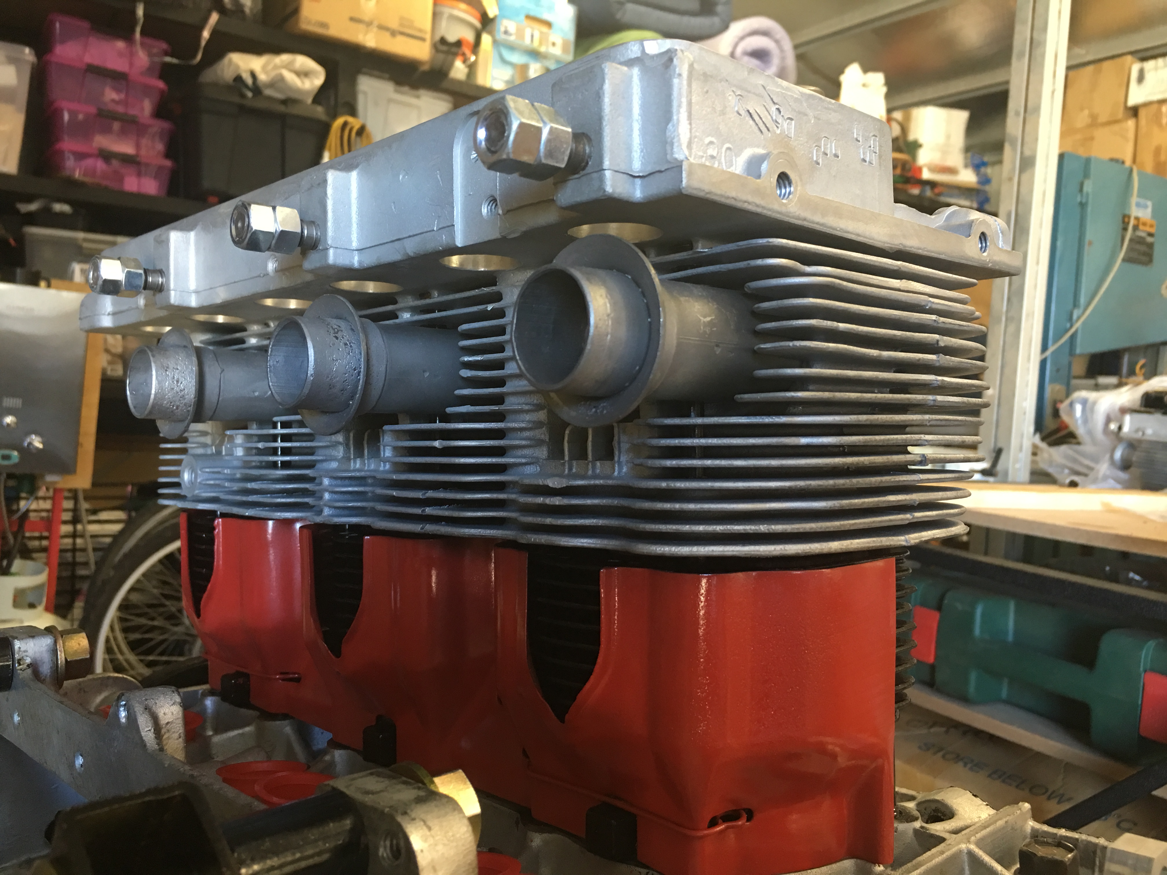
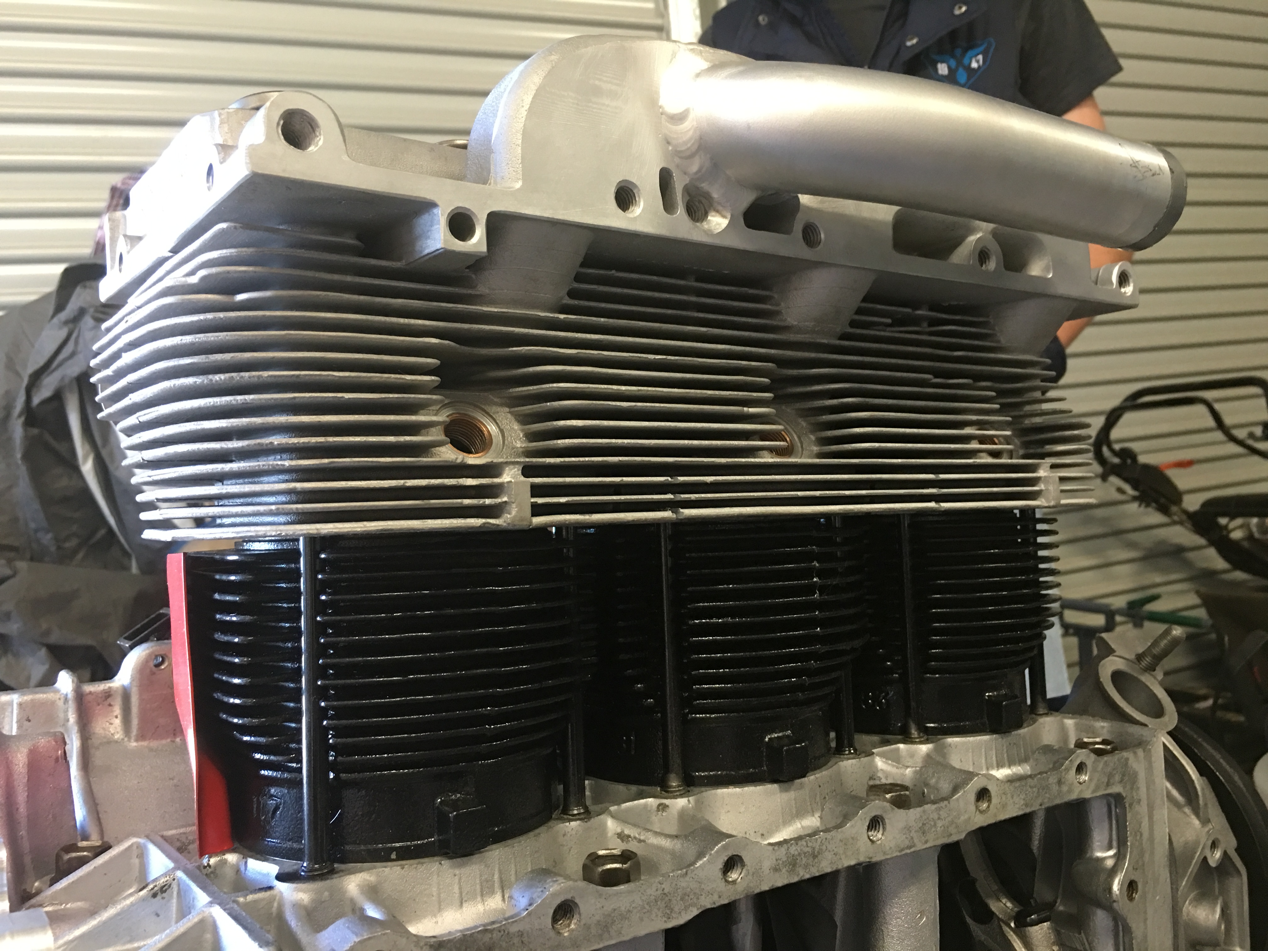
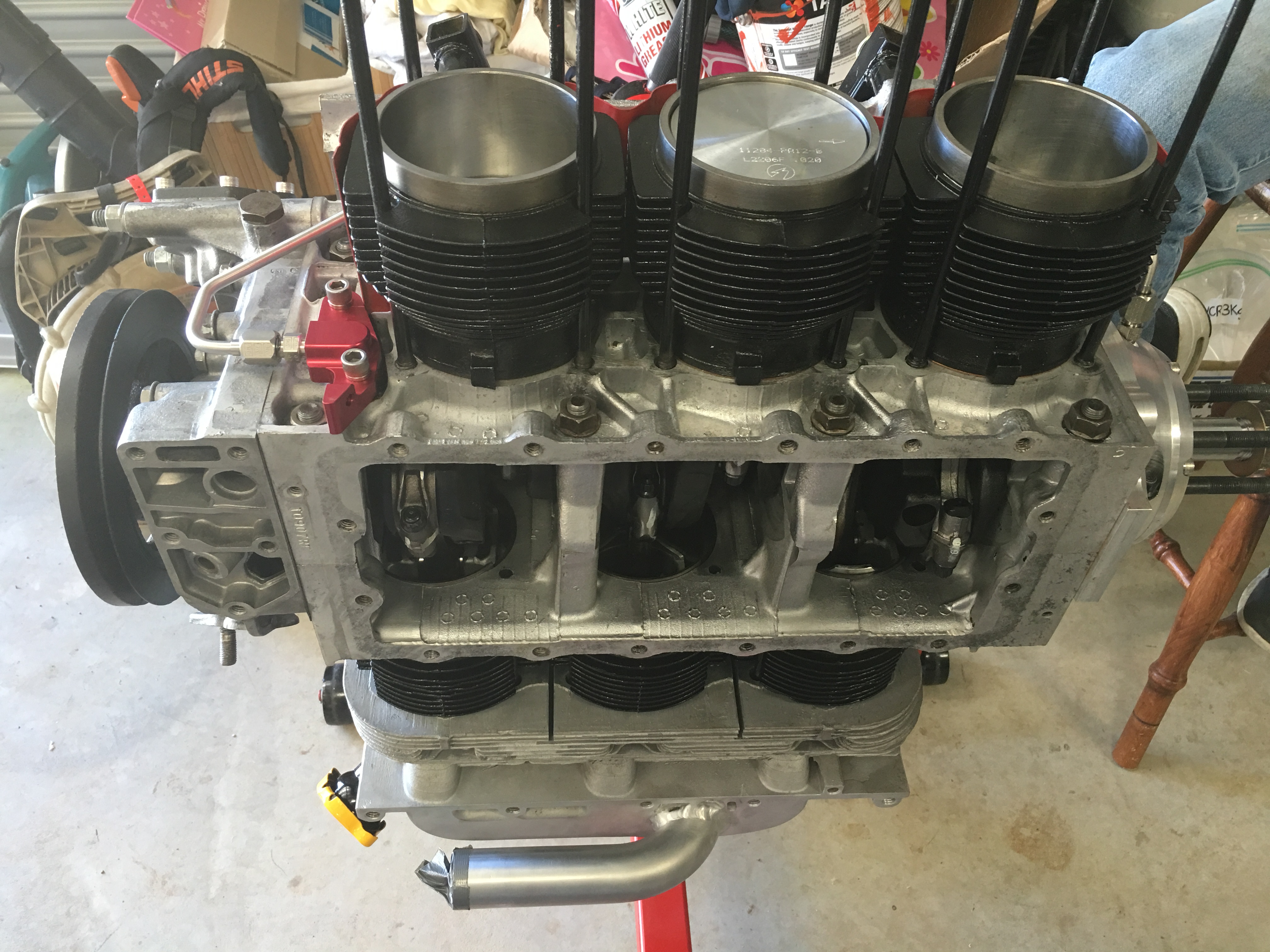
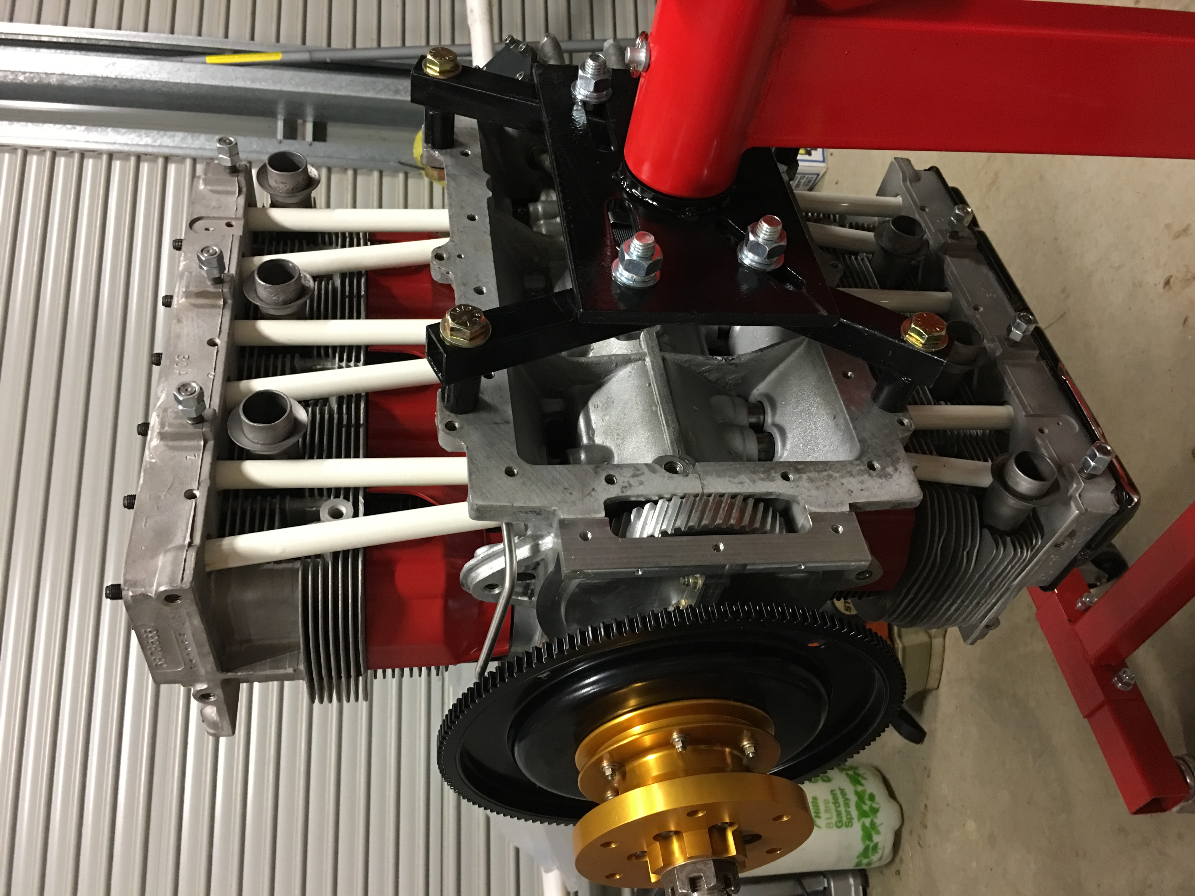
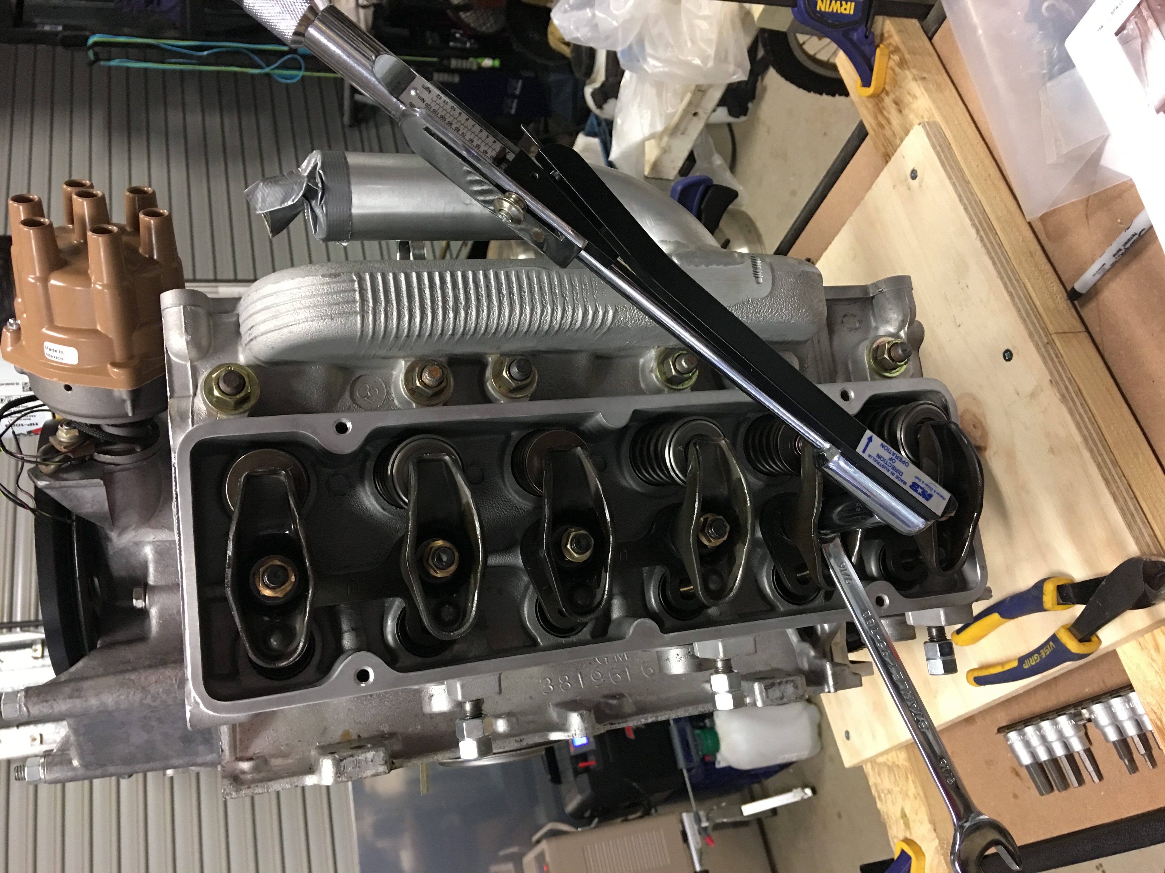
2-4-6 cylinder side head torqued down with pushrod tubes.


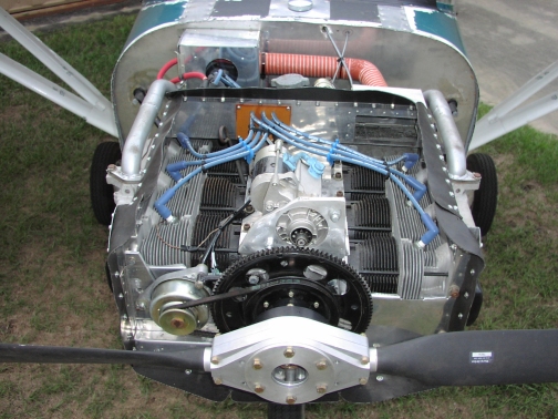
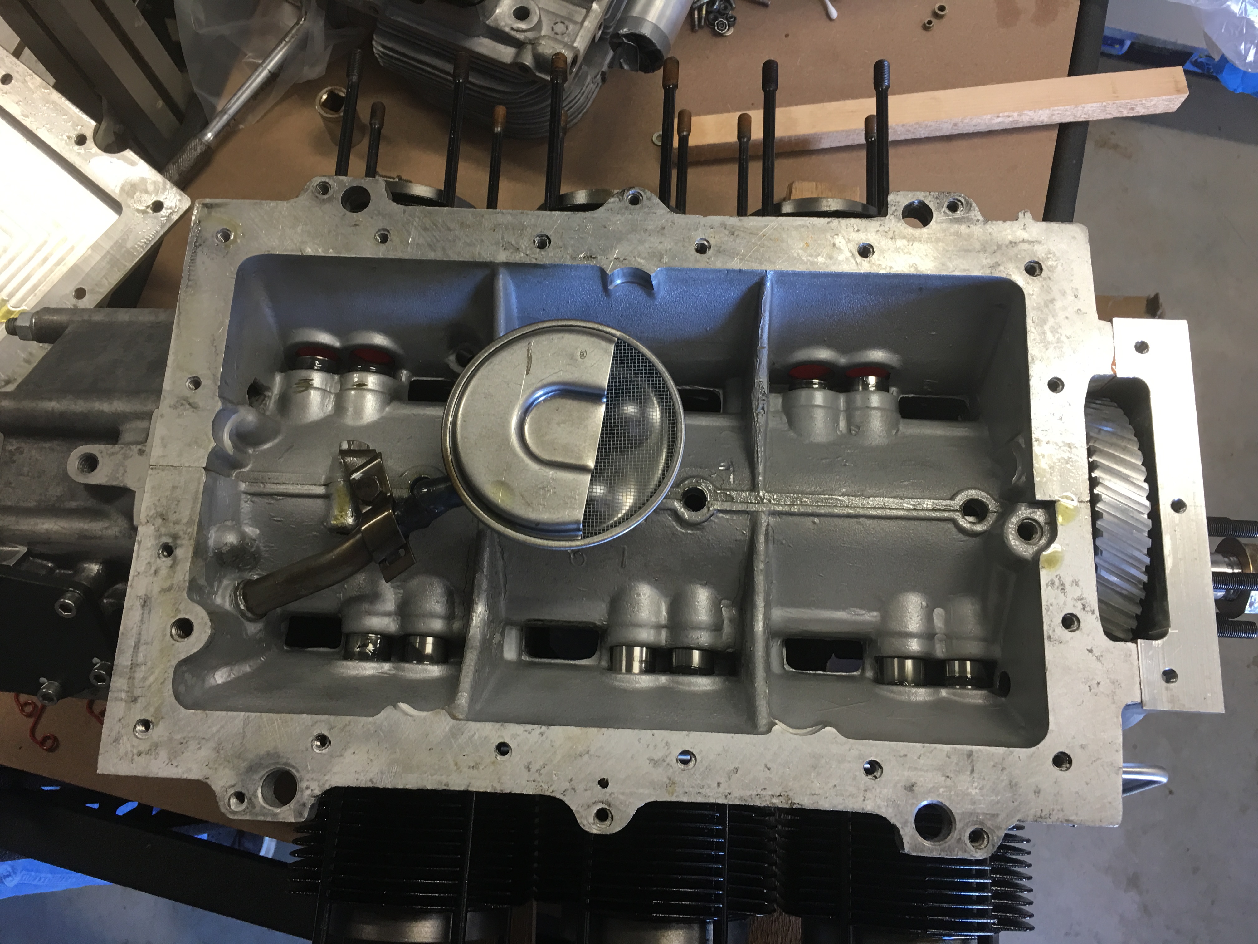
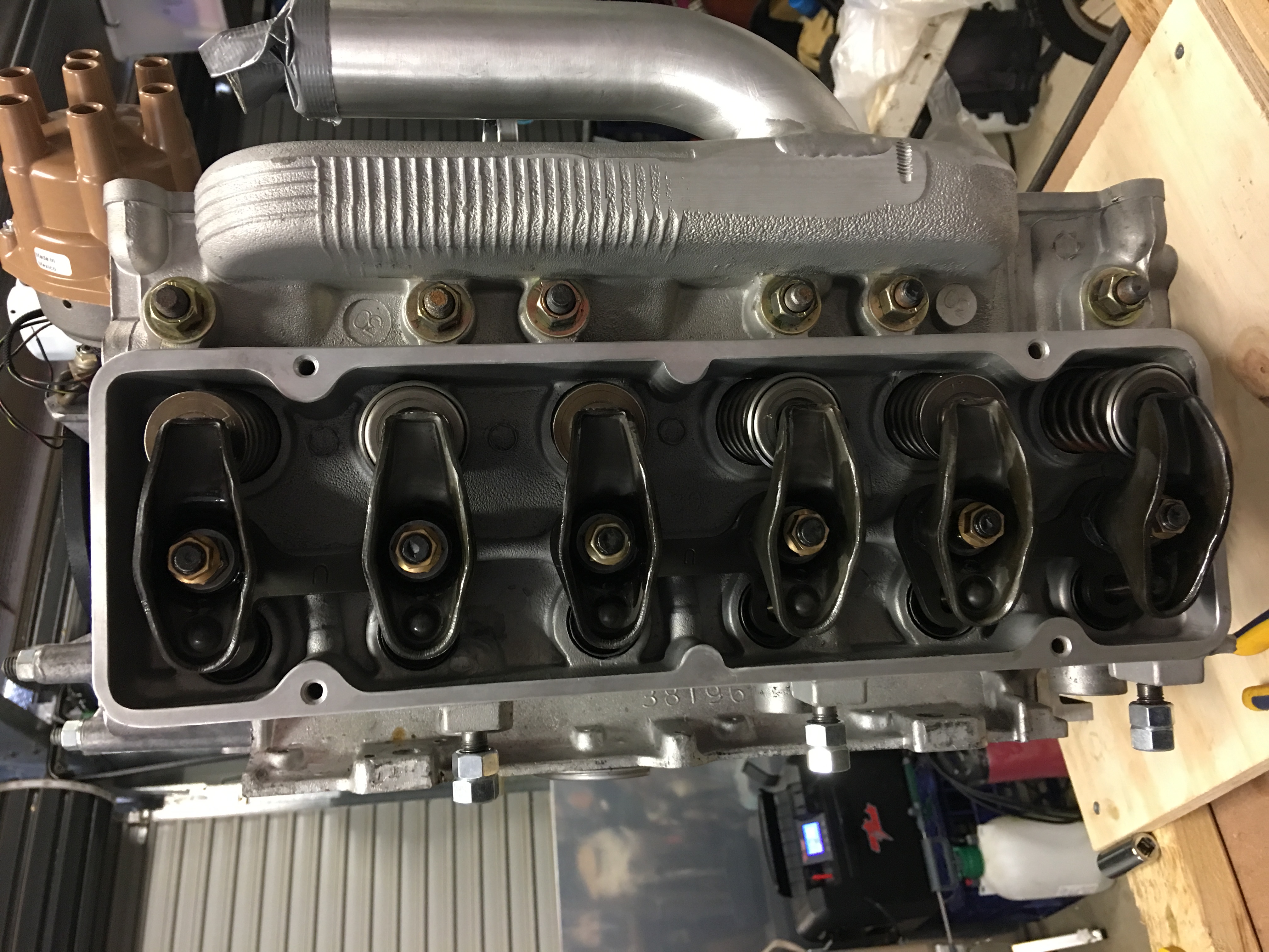
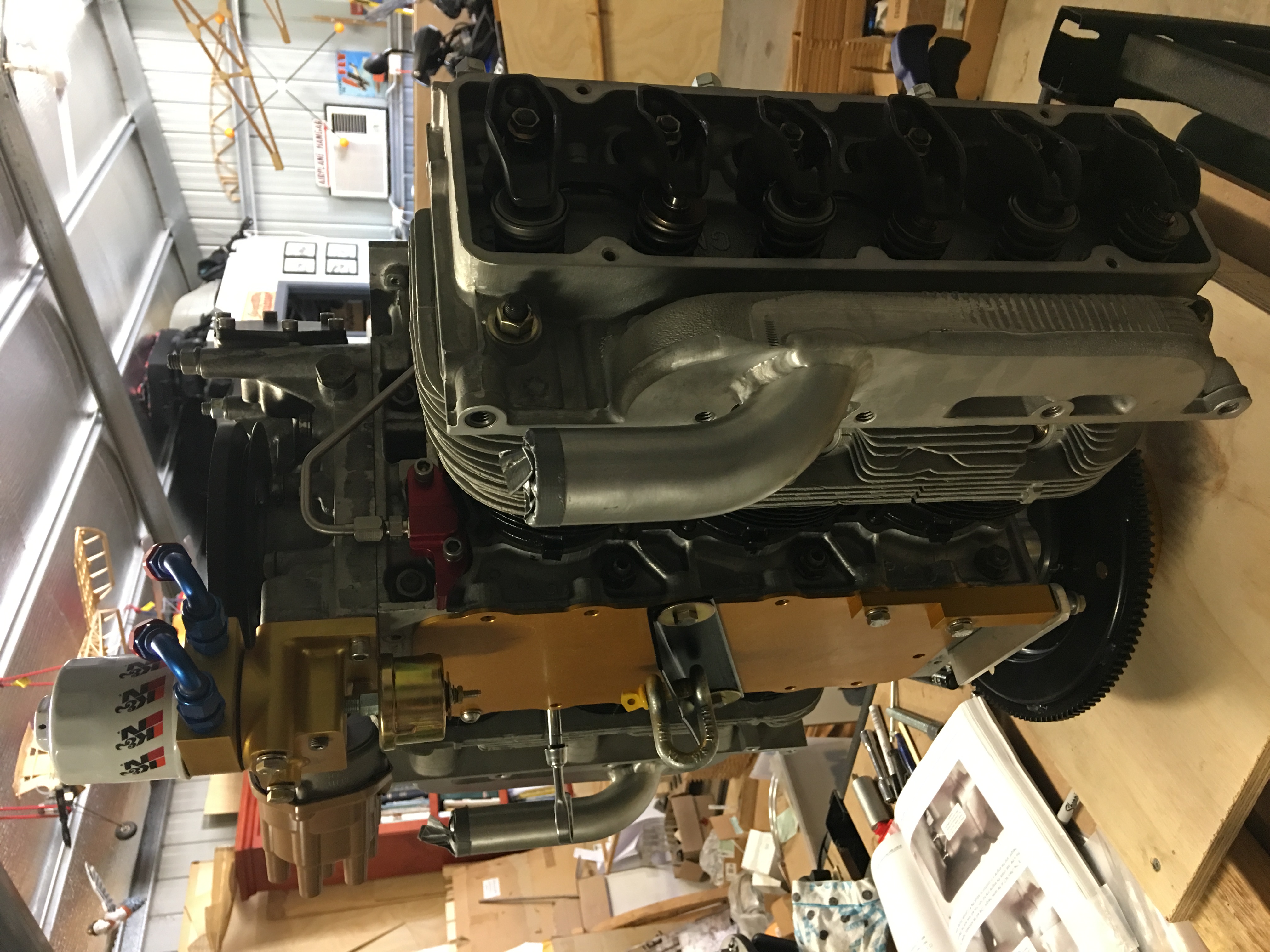
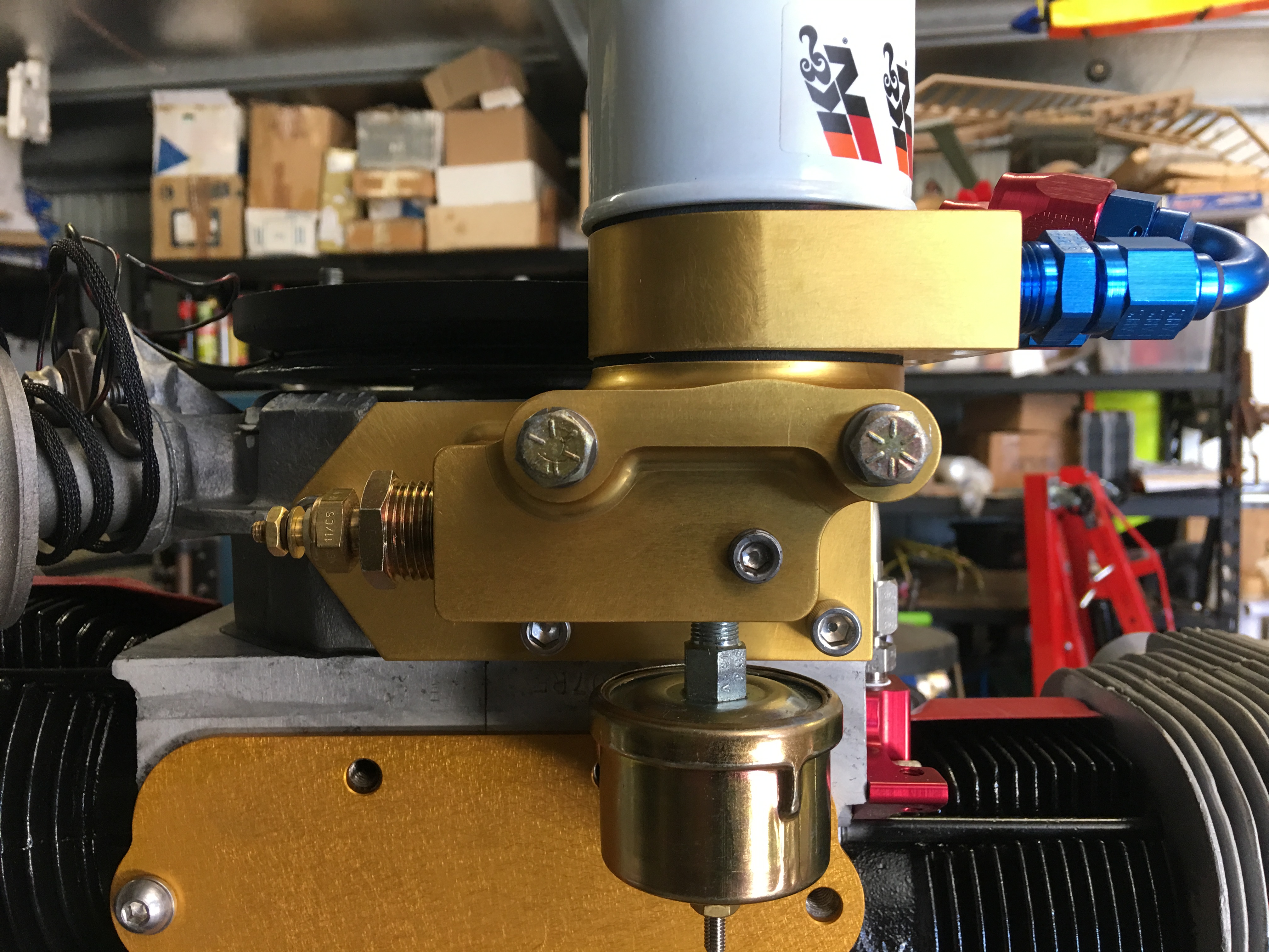
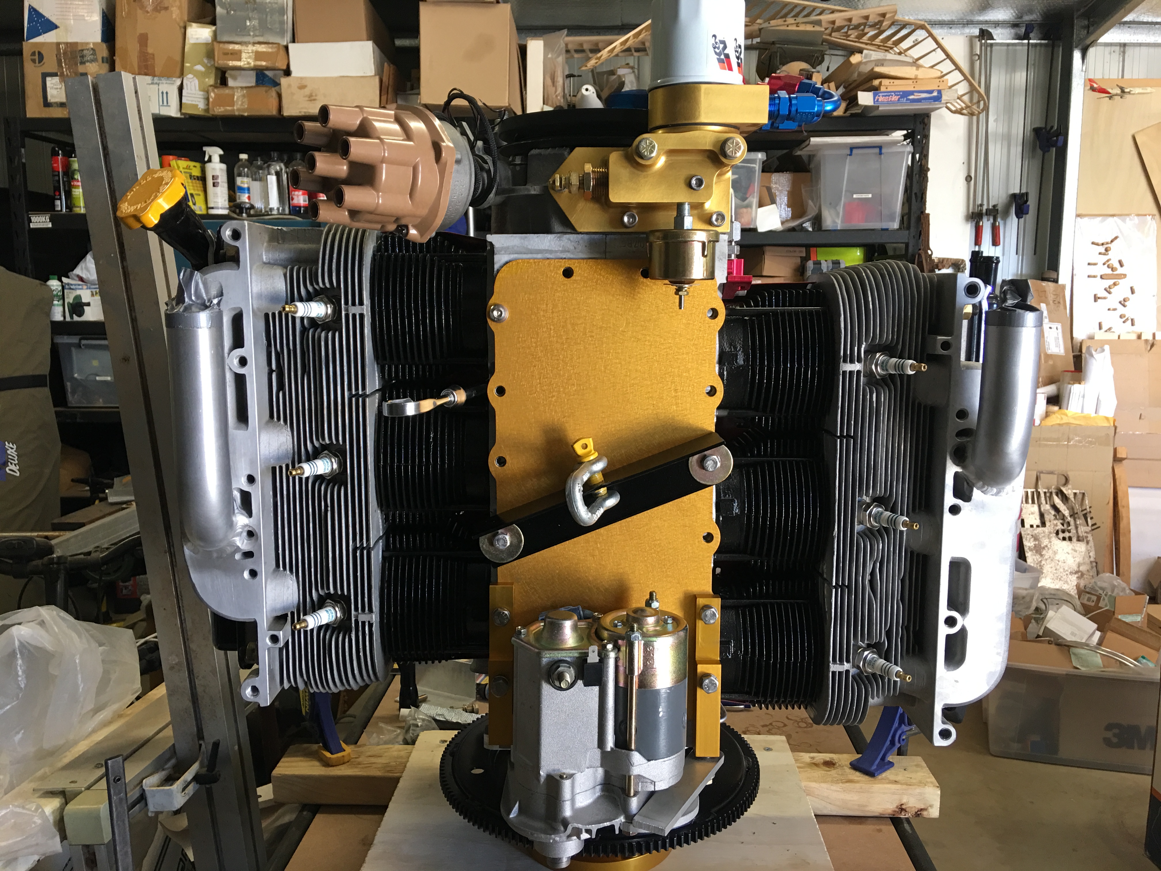
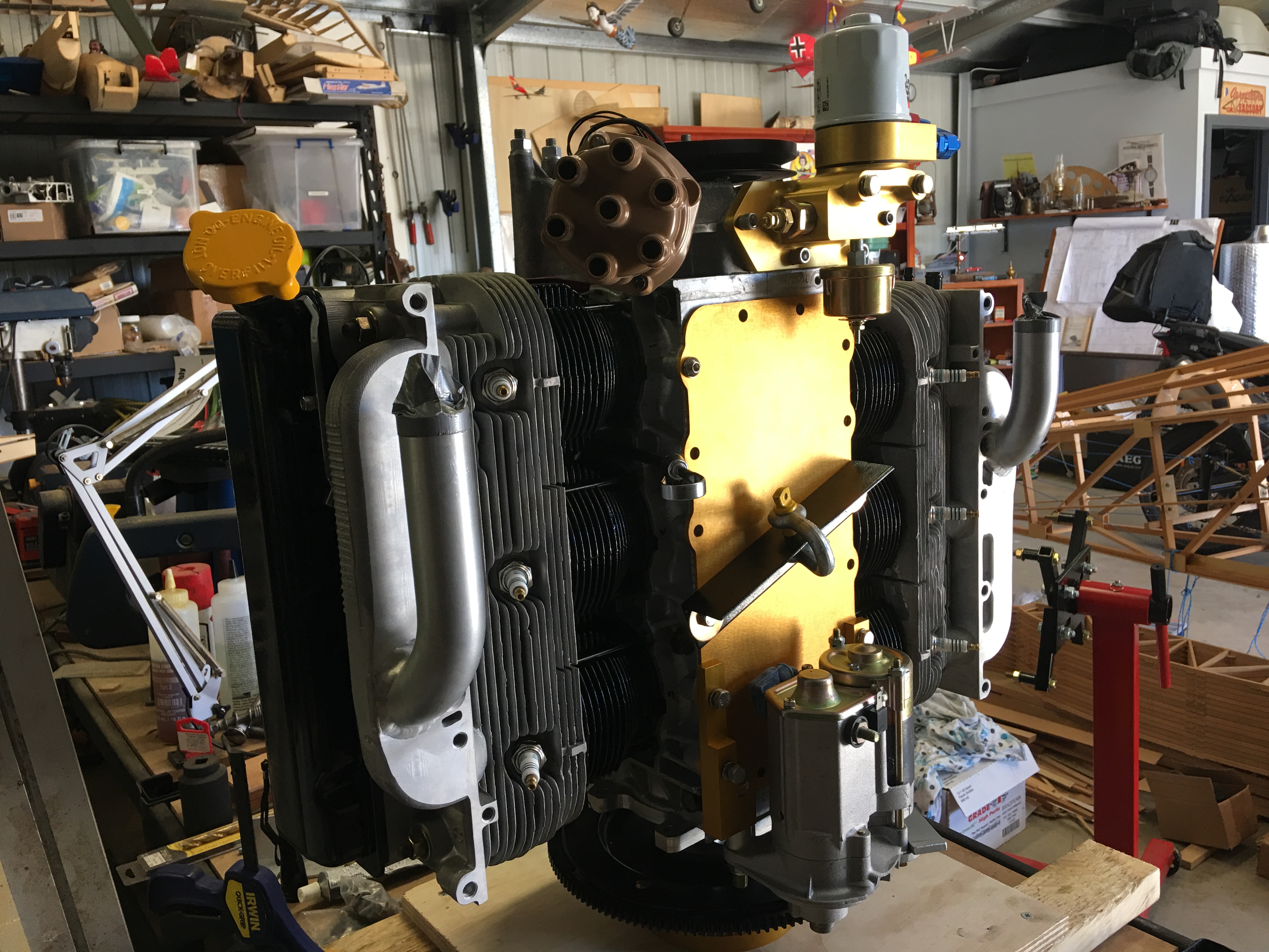
Final assembly. Pushrods and rockers fitted and adjusted. Oil pan fitted and oil system installed...


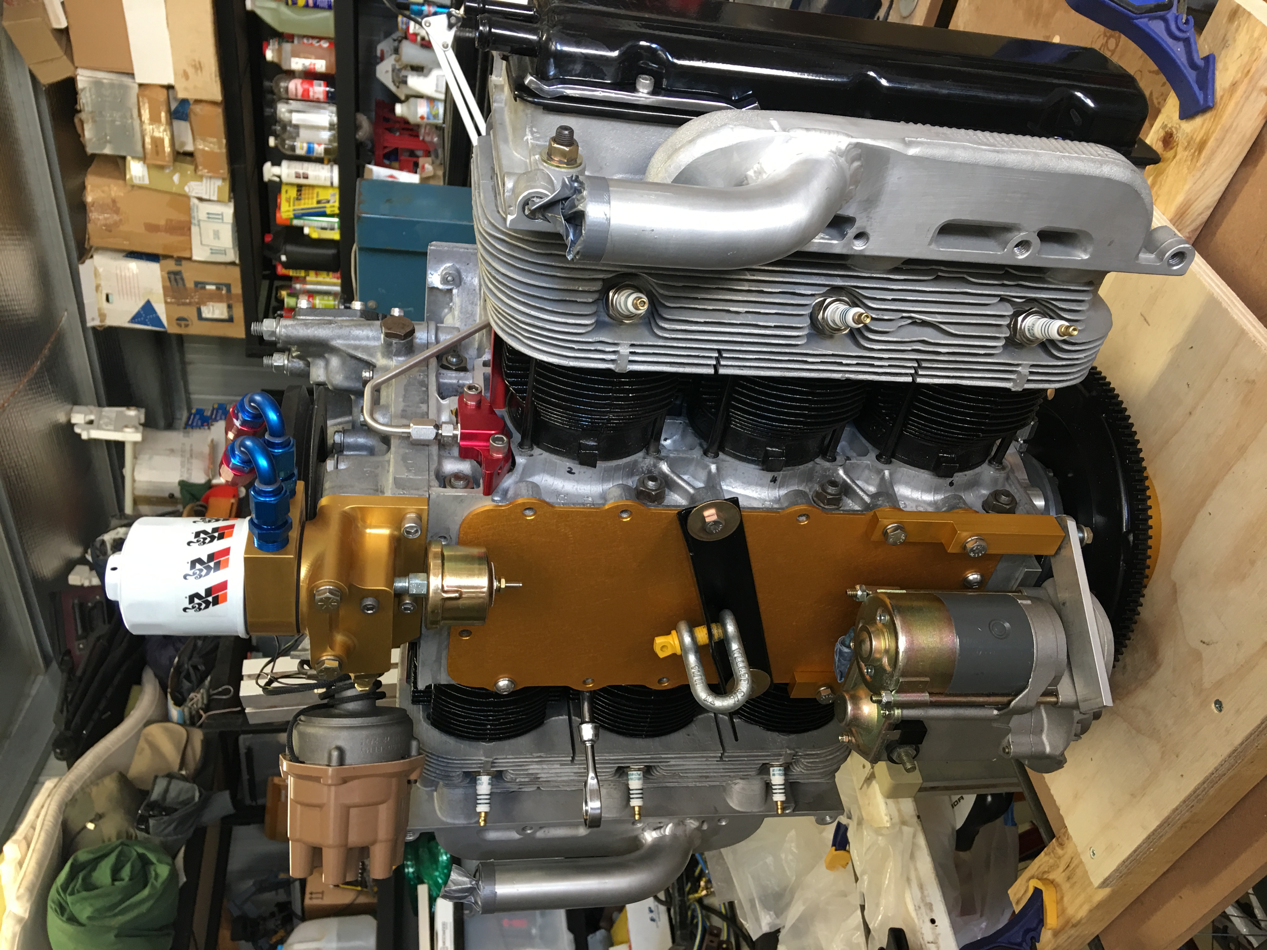
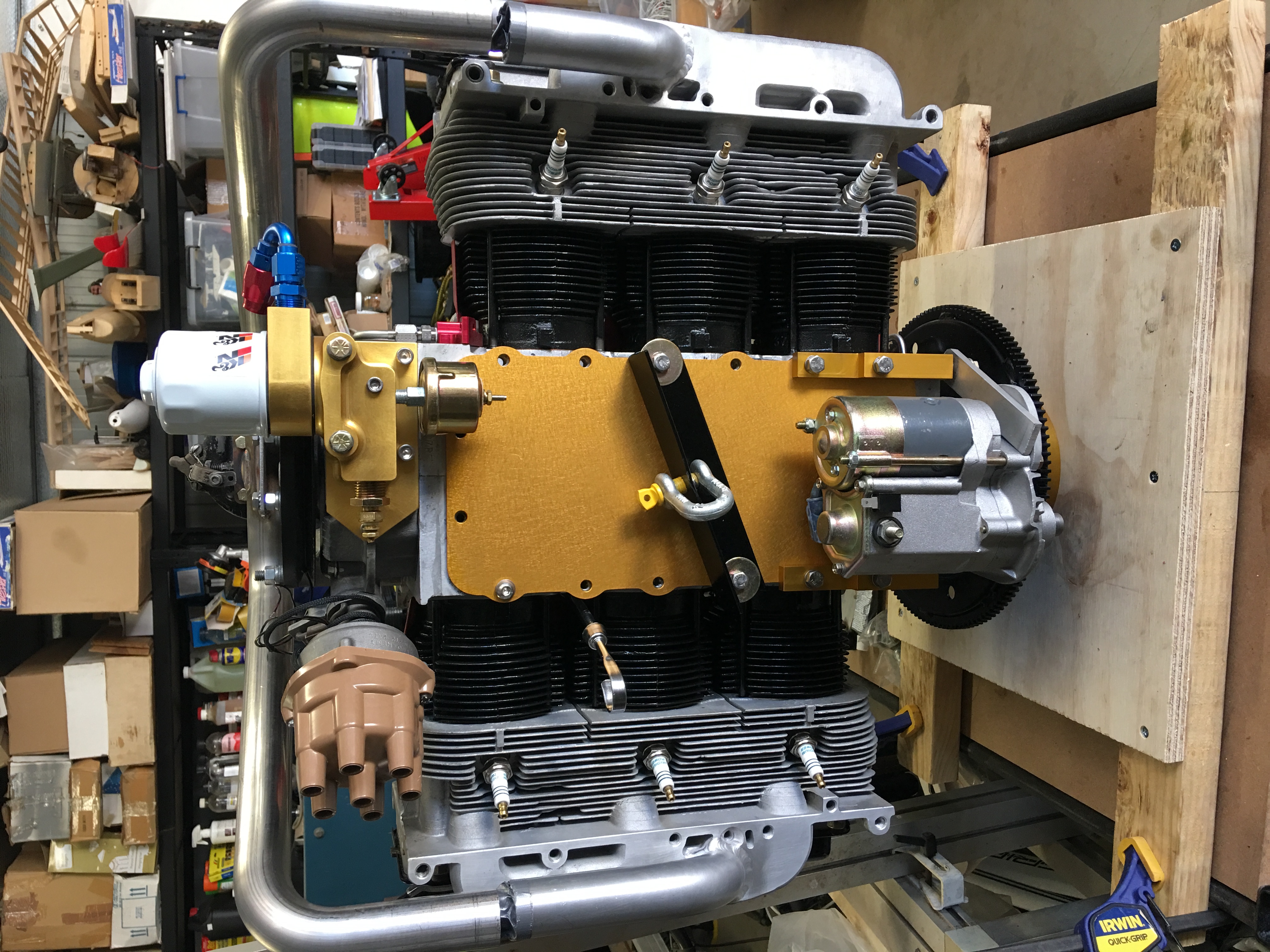
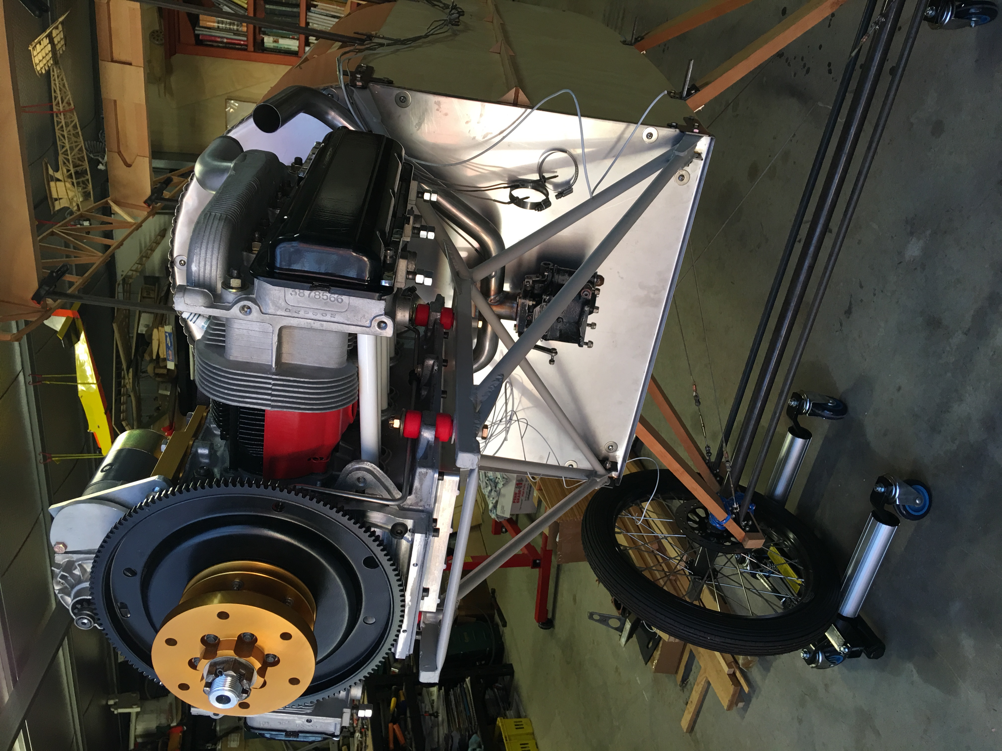
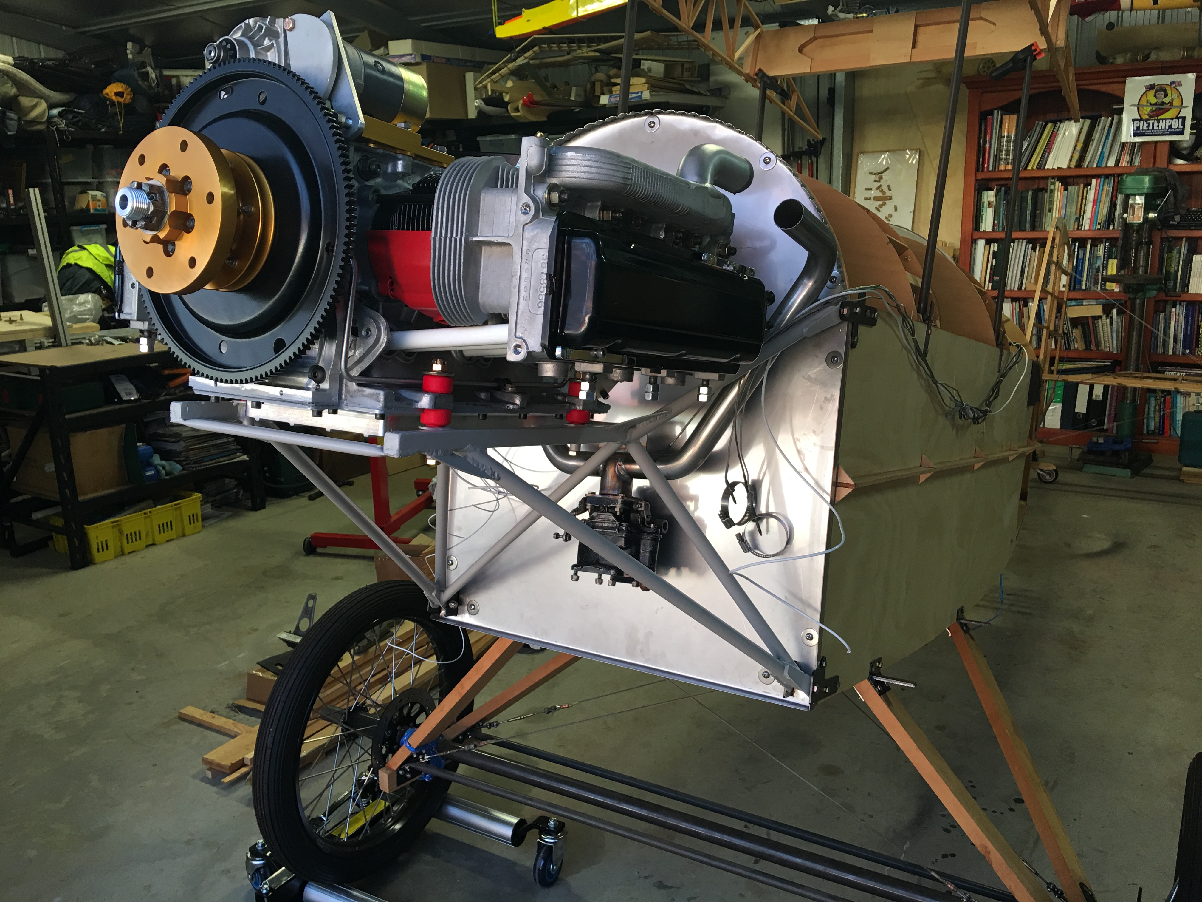
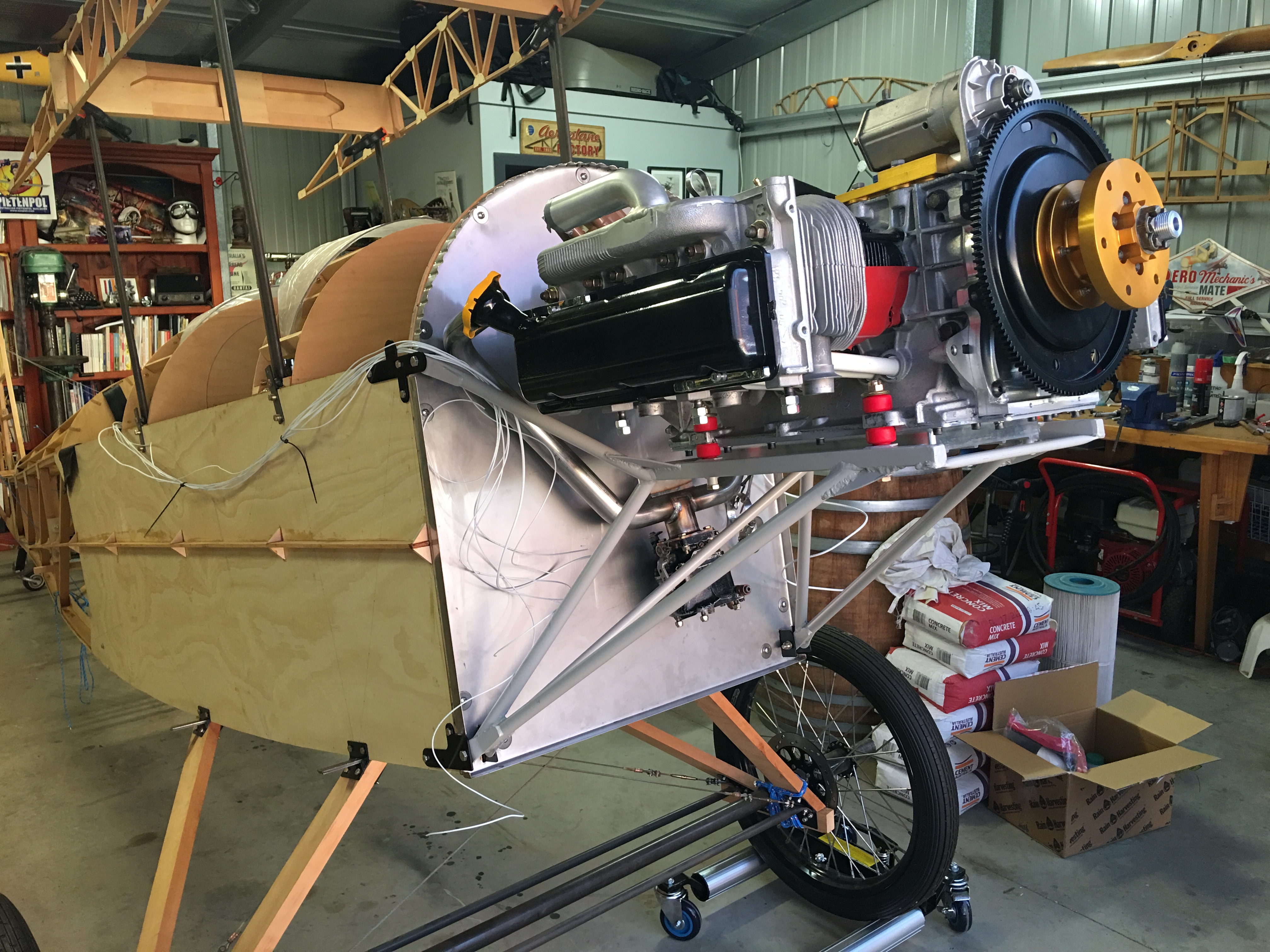
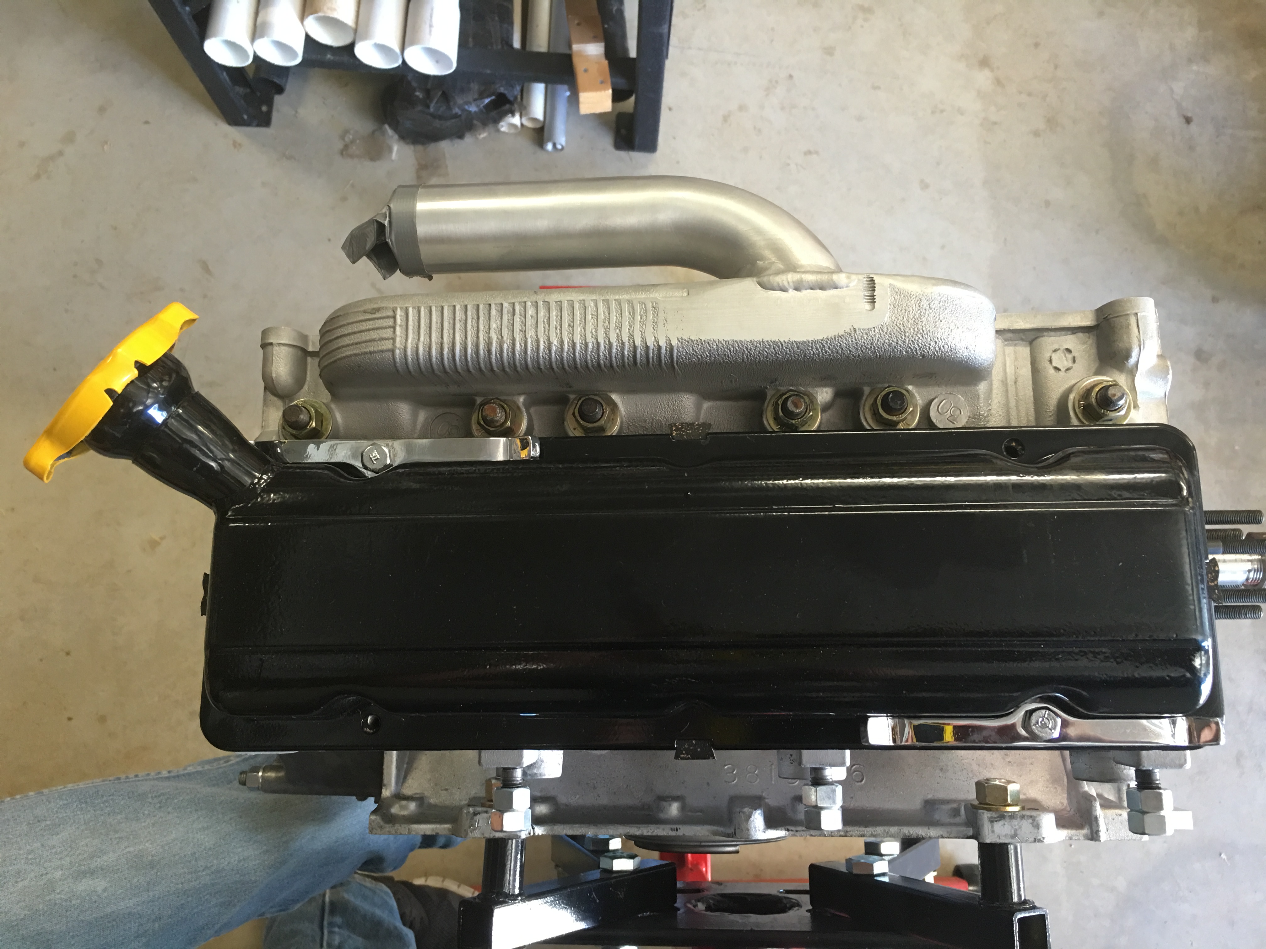
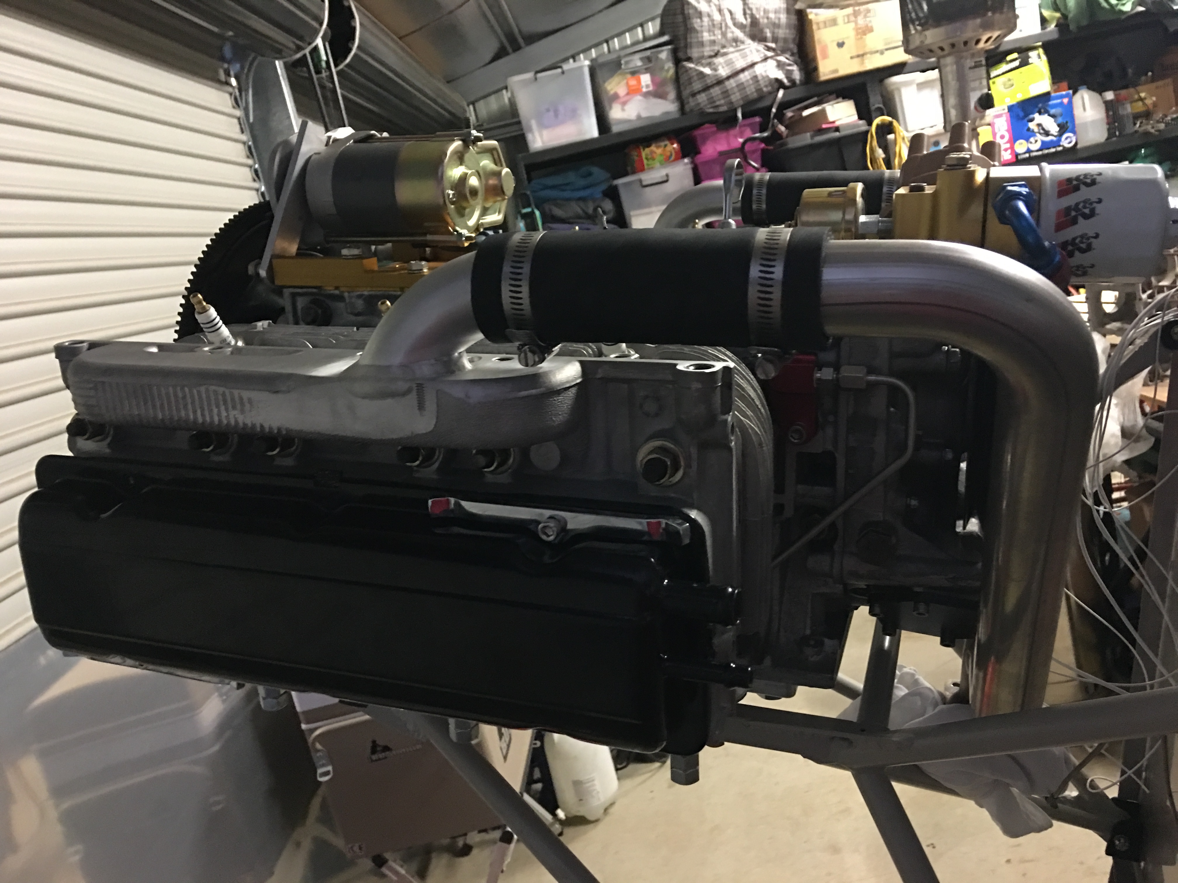
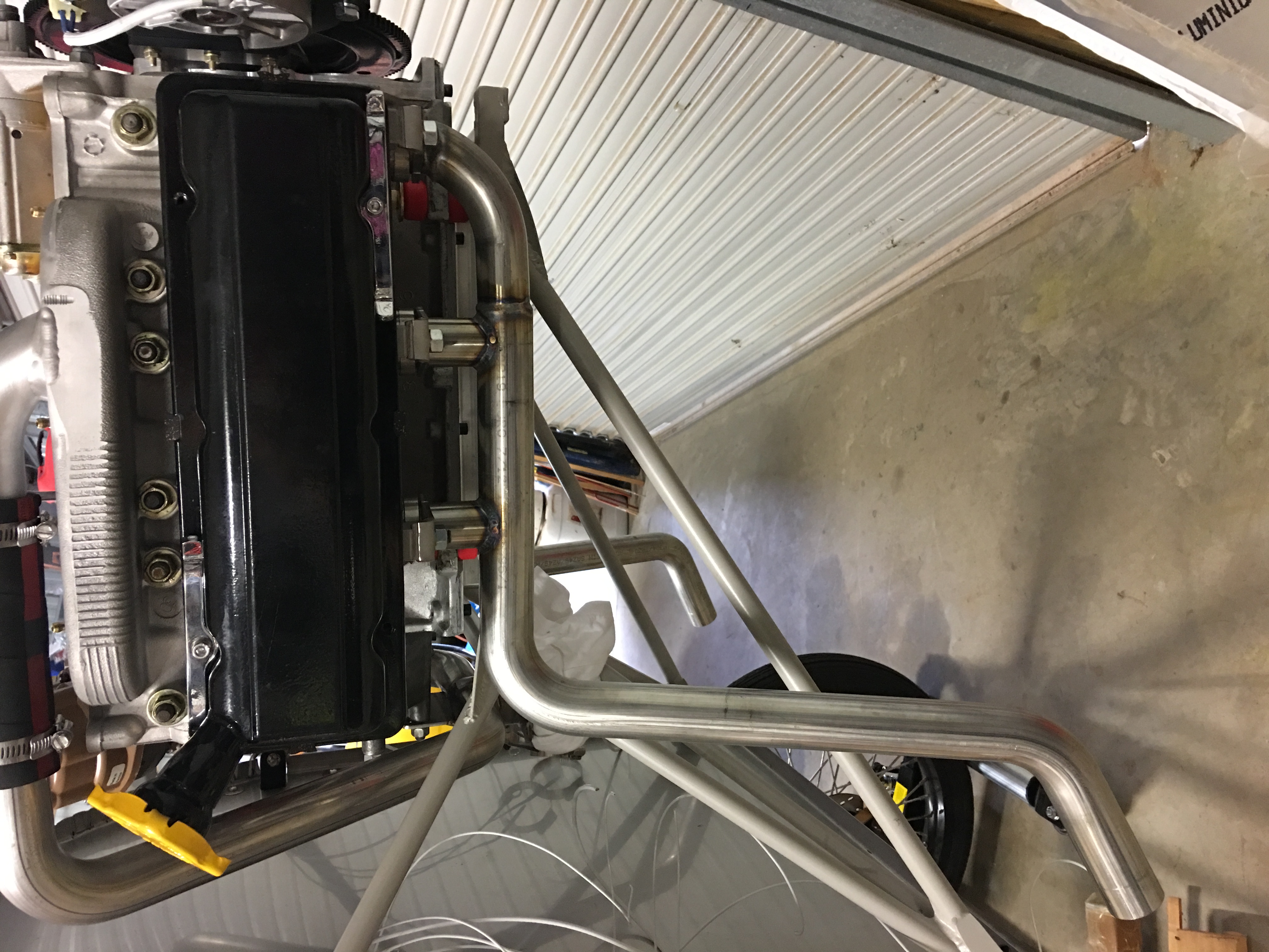
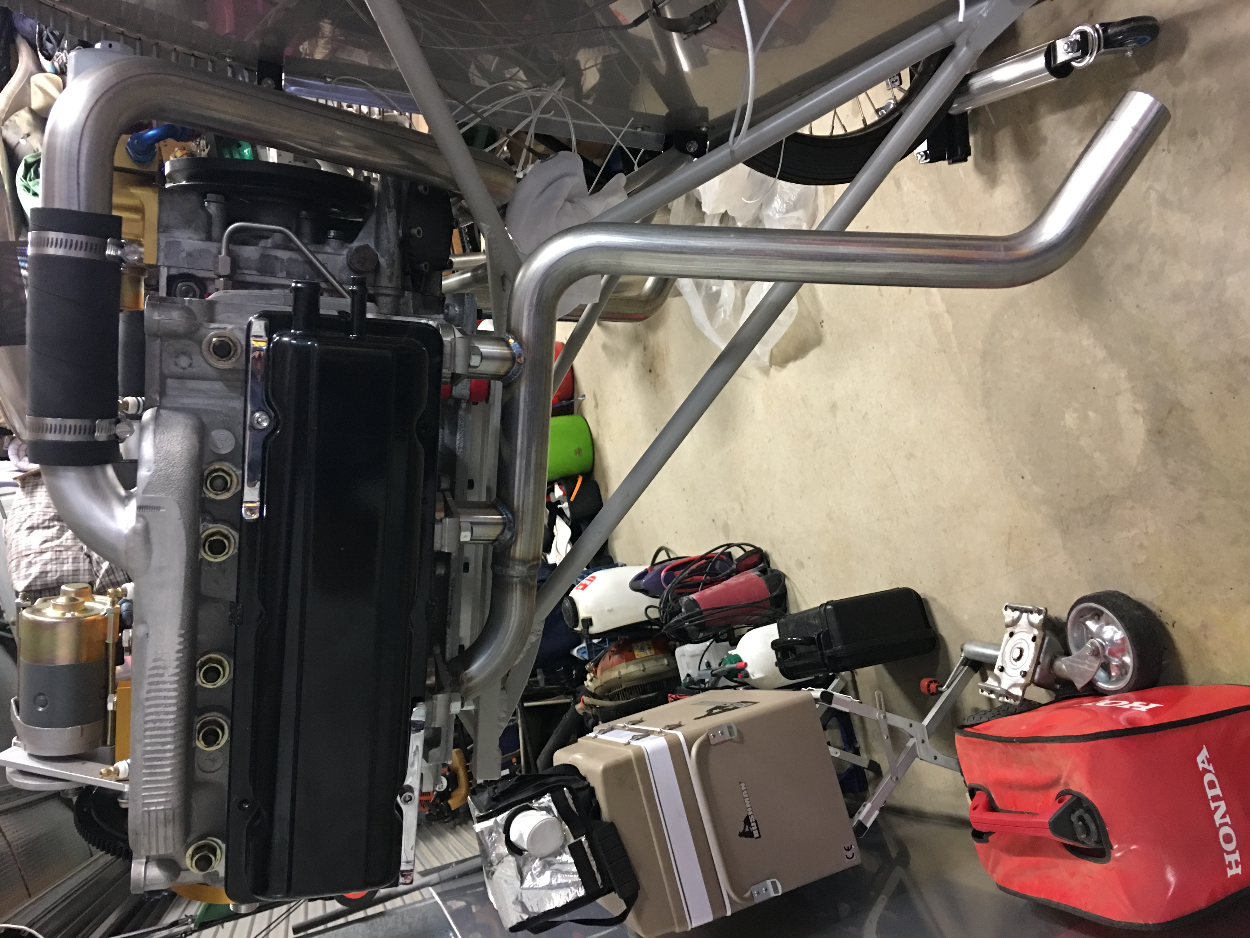
Alternator, Exhaust and Iinlet manifold...
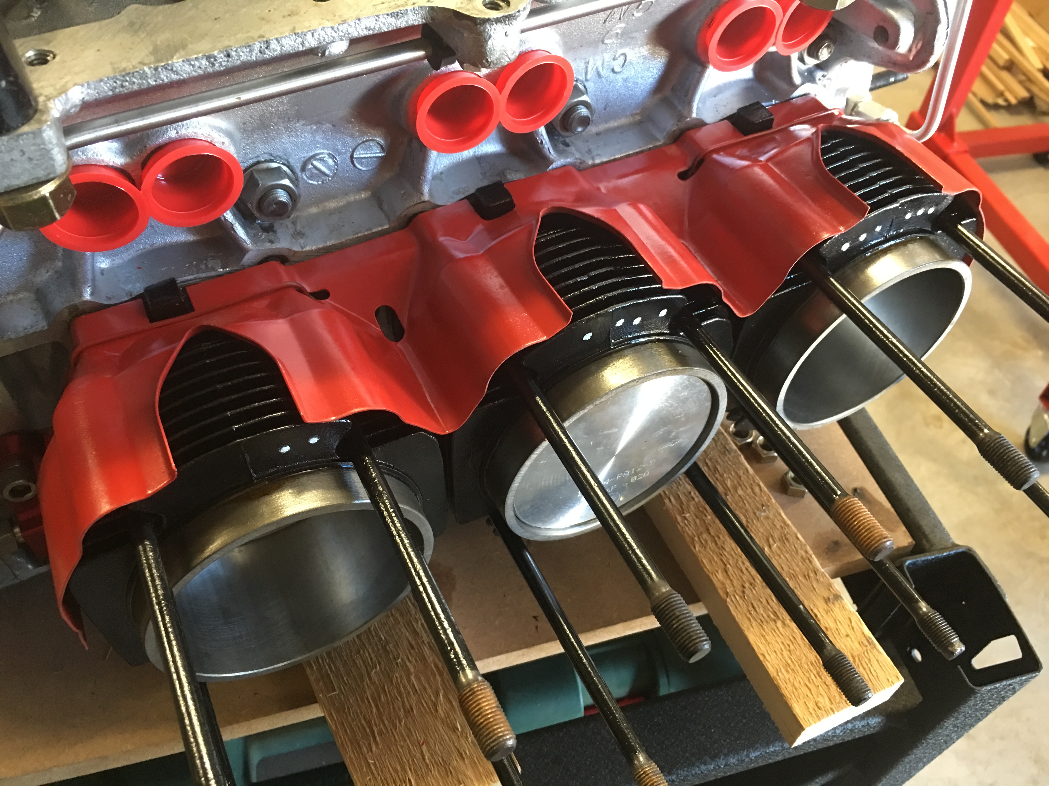
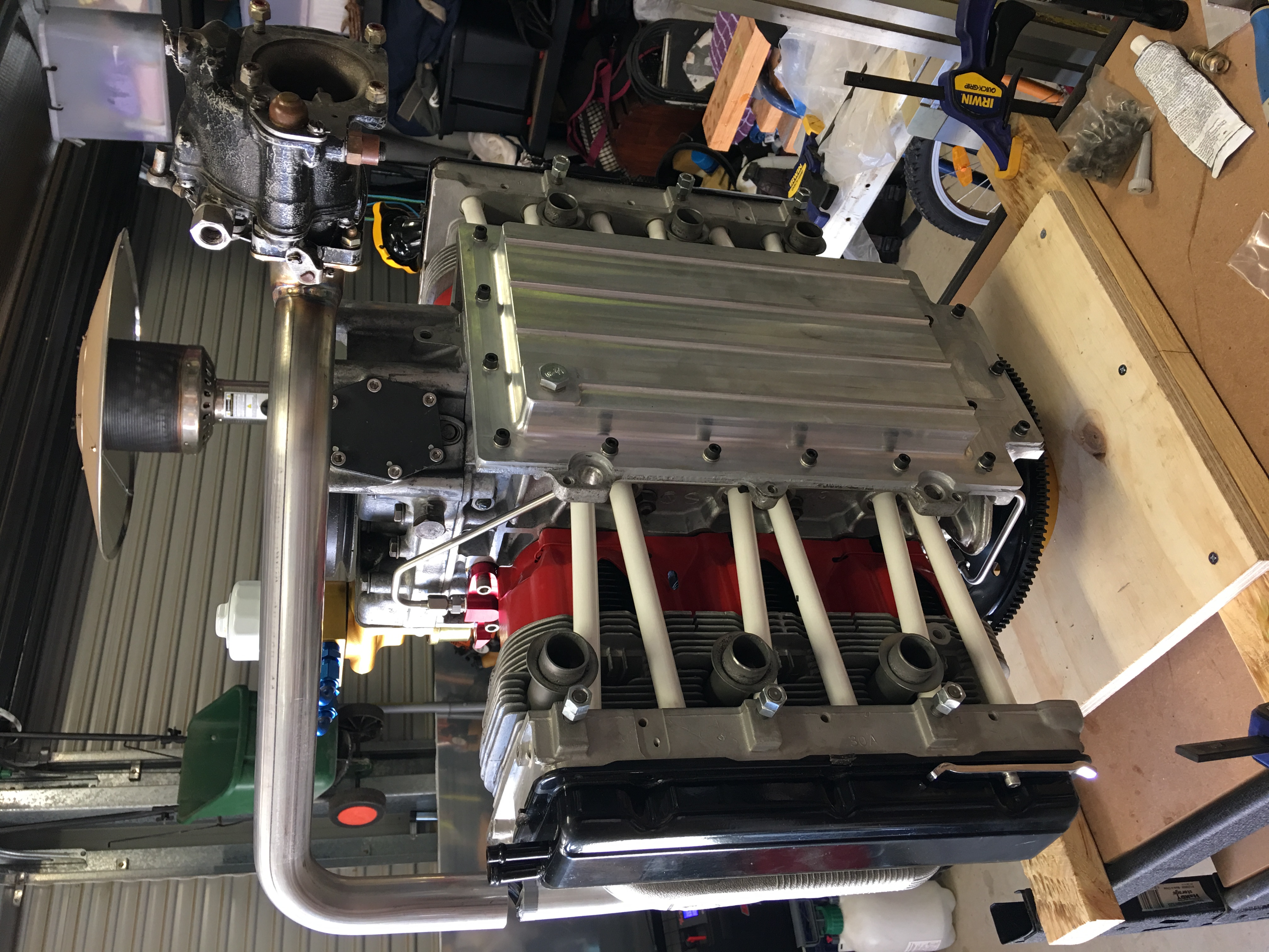
Cardboard mock-up of the cooling eyebrows and oil cooler shroud...