Started work on the turtle deck. I made a cardboard mockup of the forward and aft frame and once I was happy with the angles, I remade them in ply...
It was time to pull her out of the garage and line the horizontal stab up so the rear turtle deck former could be glued on. I drove a nail in to the centre of the front of the fuselage and hooked my tape measure on to it and measured both sides to the front corners of the horizontal stab. I was amazed that they were exactly the same! I then allowed 2mm for the covering and paint and glued the former in place...
I made the turtle deck front former with a parcel tray opening and door. I made the former out of 3mm ply and then put a doubler behind it for extra strength...
Glueing the doubler to the front turtle deck former. Once the glue dried, the edges were cleaned up and the door trimmed to fit. I fitted brass hinges and pull ring. Once all lined up, I glued the first stringer in place...
Cut out and glued the turtle deck centre support sections. Once this was all trued, I used a string line and cut the notches for the remaining stringers and glued them in...
Turtle deck basically complete...
Working on the instrument panels and thought I would bring it out again and assemble what I have done...
Instrument hole cutting and the access panel into the rear of the instruments cut out...
30th March 2014 and she stands on her on 3 feet!
Fuselage engine mount metal fittings installed...
Side parcel tray cut outs done and glued on...
Rear seat I have made a removeable centre section for easier access to underneath once it is finished...
Left side of fuselage sheeted...
A good way to move the Piet around in the garage is to put these dolly's under the main wheels...
Right side of Fuselage sheeted...
At this point in time, I am looking at covering the aircraft with the Stewart System. I keep an eye out on Ebay and places like that and when something comes up I will need down the track, I will buy it if its a bargain. I recently won these two pair of dress making scissors and a pair of pinking shears which I will need when it comes time too cover.
Wiring of rear cockpit instruments and ignition system. Making mockup of battery holder from cardboard...
Battery holder made out of 6061-T6. Am planning on mounting the Master Solenoid to the battery box...
After studying the plans and Peter Johnson's superb website, I have decided to borrow Peter's idea and use AN eyebolts for the elevator and rudder hinges. BHP plans use a similar system but needs welding. I'm not a very accomplished welder...yet!
*UPDATE - After speaking with a LAME friend he suggested I make the eye bolts central and use AN washers of similar metal, to guard against corrosion, either side of the central eye bolt. Peter has used the original idea on his with no troubles but having the washers will add to the bearing service. *
I collected the Spruce for the Empennage from Tom in Newcastle today - 18th July 2010.
*There is a discrepancy in the measurements on the plan. If you build to the plan dimensions the rudder will be slightly too long. I didn't see this till after I built the rudder but just added the difference to the top of the vertical stabiliser. *
RUDDER
After clearing a space on my building bench, I screwed a square strip of oak to the edge as a straight guide to build the leading and trailing edges of the rudder. Rather than rebating one solid piece of spruce, I glued two pieces together to achieve the same dimensions and supposedly a stronger piece.
Rudder framed up! Its important to remember to pack under the trailing edge of the rudder and NOT build it flat on the board or it will come out deformed. Ready for glue. Have drilled the 1/4-inch holes in the leading edge of the rudder for the AN Eyebolt hinges.
Rudder is now complete. I am really enjoying using the T-88 Adhesive. It is easy to work with, can use it in all sorts of temperatures and has a long working time so you don't have too rush. So far all my glue samples have split through the wood and not the joint so all good!
VERTICAL STABILISER
Vertical stabiliser all framed up and ready to be glued. Before I glue, I will drill the holes for the eye bolt hinges as the trailing edge will be easier to hold when drilling.
Rudder & Vertical stabiliser temporarily hinged together. Will gusset vert stab when I do the Elevators.
ELEVATORS
Framing up the Elevators. Will drill hinge eyebolt holes before glueing.
HORIZONTAL STABILISER
As I did with the rest of the empennage, I screwed a straight edge along the edge of the work bench. The leading and trailing edges are two pieces glued together rather than routing the step from a single piece.
The laying out of the Horizontal Stabiliser. As can be seen in the third photo below, don't forget to pack under the leading edge and centre beam so the surface is built symmetrical. Just waiting for the two end sections to be run through a thicknesser. Once that is done, I will drill the holes for the eyebolt hinge setup and glue everything.
Eyebolt hinge holes drilled, and Horizontal Stabiliser glued together...
Horizontal stabiliser removed from jig...
Brackets to mount the tail fabricated and mounted...
Coming soon...
I was contemplating the split axle gear with Matco 6 x 8.00 wheels and hydraulic brake combo but I couldn't go past the original wooden legs and wire wheels!
Dan Helsper's beautiful example of the straight axle wooden gear.
I finally made my mind up! I looked at all sorts of spoked wheel options and it was hard to find a wheel that had everything I was looking for. The Piet uses a 1.5-inch axle and not many motorcycle rims go that big. I could have used one and sleeved the axle and created all sorts of nightmares for myself but decided to go another way. Ken Perkins in the USA makes a lovely hub that takes a 1.5-inch axle and I will get Buchanan's Spoke & Rim to supply anodized black rims and lace them with polished stainless spokes.
...and the finished product!
After much research and studying other builds, I decided to replicate what Mike Cuy used on his Piet. Mike has successfully used Comet Go-Kart brake calipers for many years and stated that there is just enough grip to hold for run up but no more. I decided that is all I need! I looked at various hydraulic systems but decided against complicating things.
Trial fit the Wag Aero tail wheel assembly.
I purchased some cheap Pine timber and ripped it down to size to make a trial set of gear legs. Better I wreck some cheap Pine first rather than Spruce...
Ripped down a piece of Ash and glued it as the support for the tail wheel spring. Once this dried, I glued a piece of 3mm ply on top and will glue a piece on the other side. Will use AN6 hardware to mount the assembly...
Fitted Avon Speed master 21" tyres that arrived from the UK. Started bending and fitting the undercarriage leg metal fittings. Eventually the sides of the fuselage will be sheeted with 3mm ply. To allow for this I have temporarily placed the pieces between the metal fitting and fuselage to allow for the spacing...
Started bending and fitting the undercarriage leg metal fittings. Eventually the sides of the fuselage will be sheeted with 3mm ply. To allow for this, I have temporarily placed the pieces between the metal fitting and fuselage to allow for the spacing...
Making the wheel axle collars...
Fuselage turned upside down and I marked the line so the axle can be aligned...
Rather than re-invent the wheel, here is the link to the West Coast Piet site that has a fantastic description of how to build the "Jenny" style wooden gear. I followed this step by step and it worked! I used some Pine I ripped down to size first so I didn't destroy my good Spruce if I got it wrong!
Im happy with the angles and the mock gear legs. Now to start ripping down Spruce for the actual undercarriage legs...
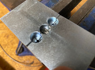
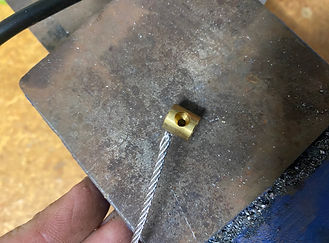
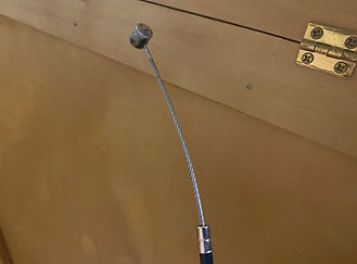
Spruce legs are in! Also had my first attempt at making a Nicopress swage loop which will be needed for the undercarriage brace wires and control surface cables...
Started cutting out the lower gear leg metal fittings. Procrastinated far too long about these so grabbed a hacksaw and some cutting oil and didn't take too long...
Metal gear fittings nearly finished. There is a lot of work involved in this undercarriage!...
Spreader bars made and fitted. I tried the method most use of making dies to place in a vise and heating and crushing the tube. It was dam awkward! After the first one I heated the tube cherry red and then beat it flat with a flat faced hammer. It worked great. Where the flat joins the tube I used a piece of tube and hit it with a hammer to form the radius. I found it much easier. Gear cable fittings bent and fitted and about to make cables...
30th March 2014 and she stands on her own 3 feet for the first time. Waiting for clevis pins to be able to mount the gear cables...
Gear tension cables made and fitted. Used 1/8 cable with Nicopress swages...
Front and rear spreader braces made, painted and fitted...
Axle anti rotation setup made and welded...
Brake caliper mounting brackets made and TIG welded to axle. Brake pedals made along with the cables to operate...
I spent a lot of down time thinking how I would produce the metal fittings. Sheets of 4130AQ are very costly and you generally need to buy a minimum quantity. I thought of using a sabre saw or a metal table saw but the finish using these tools would not be optimum. I met George Abernathy from Canberra here in Australia who is very handy with CAD and is working on drawing all the metal fittings and having them laser cut. George can cut many sets out of a sheet of 4130 and has these available to purchase.
0.32" fittings
Metal work is something I enjoy but unless you have the right tools, it can be a nightmare and dam dangerous as well! I was going to buy the metal parts readymade but with the cost of freight from the USA, I decided to have a go myself! Glad I did as it didnt take long and it felt good too! I was wondering how the best way to cut the 4130 tube would be. Then the penny dropped! Some time ago I picked up an older style Makita drop saw. It is all metal and weighs a ton! They don't build tools like that anymore! I took the wood cutting blade off and a trip to the local hardware store revealed a metal cut off wheel that bolted straight on. Worked an absolute treat!
I made the front rudder pedals...
...and the control system.
I was dreading having to cut all the sheet metal and was looking at buying the parts pre-made. I took the time to research how to use a hacksaw correctly and what blades for each metal and thickness of metal and surprise surprise, with a little cutting oil, it is not as hard as I thought! I made both sets of control stick hinge plates in about 30mins...
Learning to TIG weld is the next project!
Turnbuckles for rigging.
November 2013 I organised a TIG welding course in Canberra. We had 12 guys attend and at the end of two days we had a very good grasp of the process and the guys were producing some nice welds. Here are a couple of my practice pieces...
Made a jig as outlined in an article in the BPA newsletter from Chris I believe of WestCoastPiet fame to crush the ends of the 4130 tube as required in various metal parts...
TIG welding the front rudder pedals. I'm not happy with the result so will remake them. Although it would probably hold, it looks like a dogs breakfast!...
After numerous attempts at these front rudder pedals, I finally sorted what I was doing wrong and have them done and welded the streamlined section of the control crank to the tube!
Lower cabane fittings bolted to fuselage and bolt bearing TIG welded to cabane strut...
Lower control stick fittings TIG welded, and holes drilled for mounting bolts...
Front rudder pedal mounting brackets fabricated and fitted...
Horizontal stabiliser wire brace fittings...
Rudder horn bent and Tig welded...
Elevator bell crank painted and fitted...
Elevator horns bent and TIG welded. Fitted to elevators and rope connected to check eventual control cable runs...
Aileron horn bent and TIG welded...
Elevator control cable support pulleys and brackets...
Rudder bar and post fabrication...
Crimping and folding the top section of the firewall with Fluting pliers...
Stainless fire wall secured to ply backing...
Connecting rods between rudder bar and front rudder pedals fabricated and fitted...